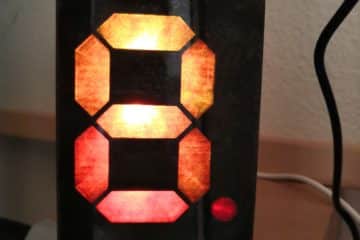
This time I will show how I built the LED light cubes shown in the picture above. I call them TinyLightCube, as they using an ATtiny85 as a microcontroller. The cubes will change their color depending on how they are tilted.
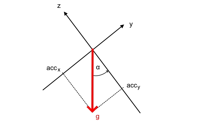
To get the tilt angle I use a 3 axis acceleration sensor and calculate the gravitational acceleration vector  between the y-axis and z-axis.
![\[ \alpha = \arctan(\frac{acc_y}{acc_z}) * \frac{1}{(\pi * 180°)} + 90° \]](https://techniccontroller.com/wp-content/ql-cache/quicklatex.com-95d77e6dbb038fd458857dbfffe62600_l3.png "Rendered by QuickLaTeX.com")
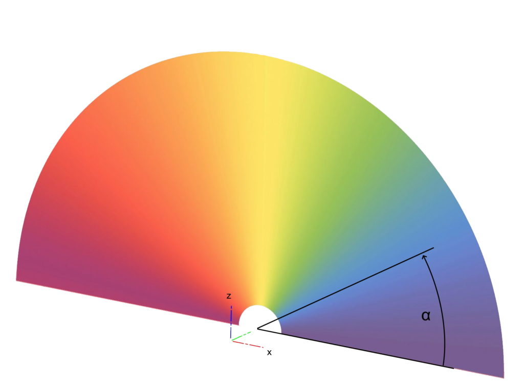
I mapped this angle  then to an color circle which goes from
  (blue) to
  (red). If the angle is larger than 180° it starts from beginning.
Parts
For one color cube we need following parts:
- Attiny85
- 6x NeoPixel WS2812b
- AZDelivery TP4056 Micro USB 5V 1A Charge Controller Lithium Li-ion Battery Charger (amazon.de*)
- MPU-6050 GY-521 3 Axis Accelerometer Gyroscope Module (amazon.de*)
- LiPo Battery 3,7V 250 mAh 27x25x6mm 602025 (amazon.de*)
- some header pins and cables
- 3D print: transparent PLA filament
* The links are affiliate links. The offers do not come from me, however, I receive a commission through the reference, if then a purchase takes place, but without you incurring additional costs.
Schematic
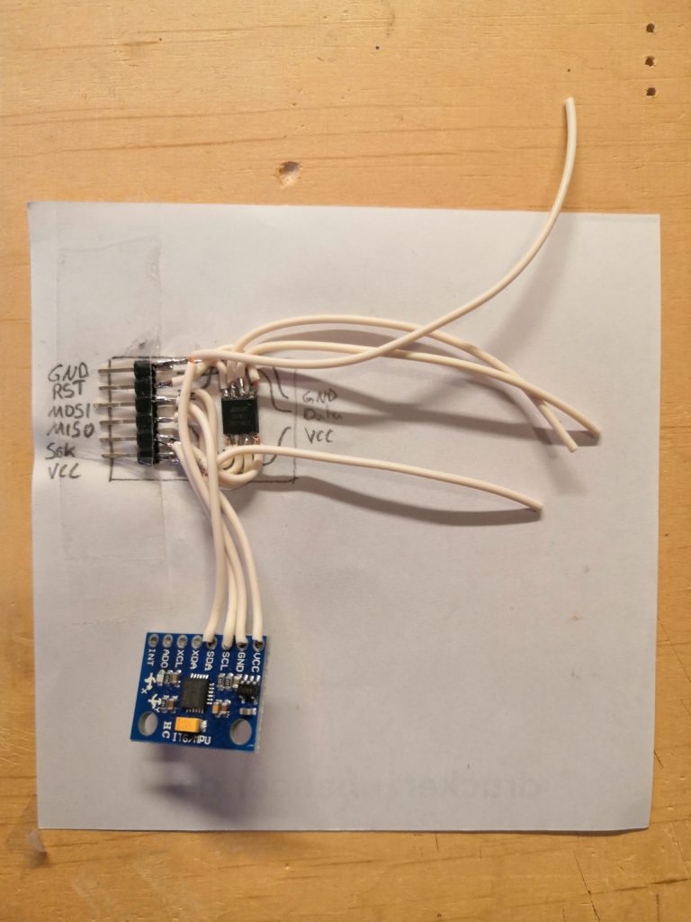
The electronic circuit of the LED light cube looks like that. You can see it is mostly just a combination of the different modules:
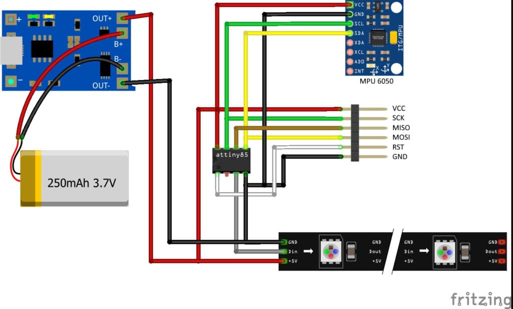
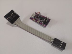
The 6pin header is used to program the Attiny85 with an ISP Programmer. I am using the USBtinyISP, which is easy to handle.
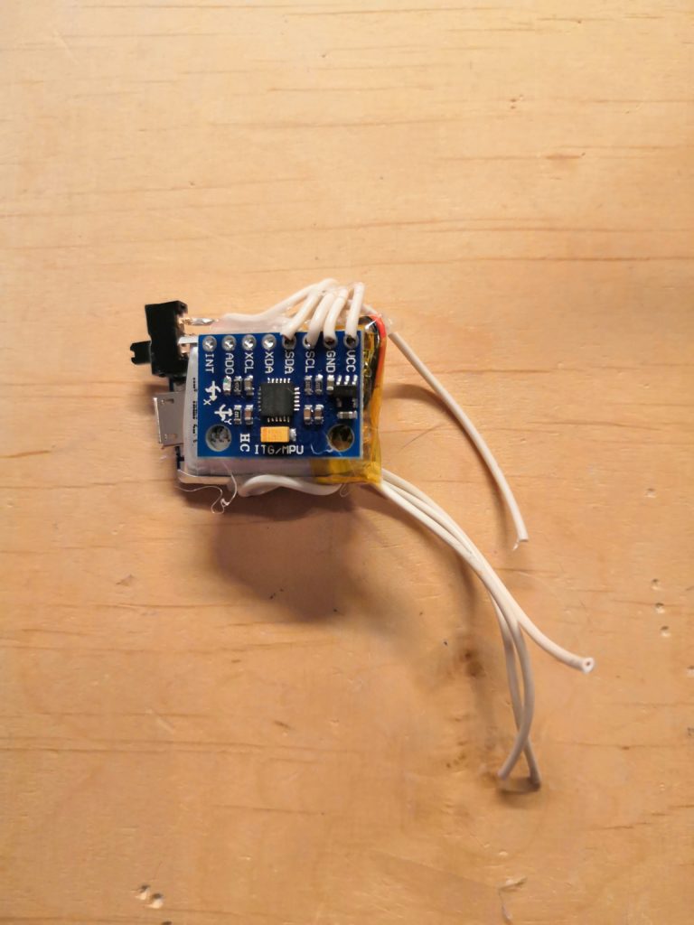
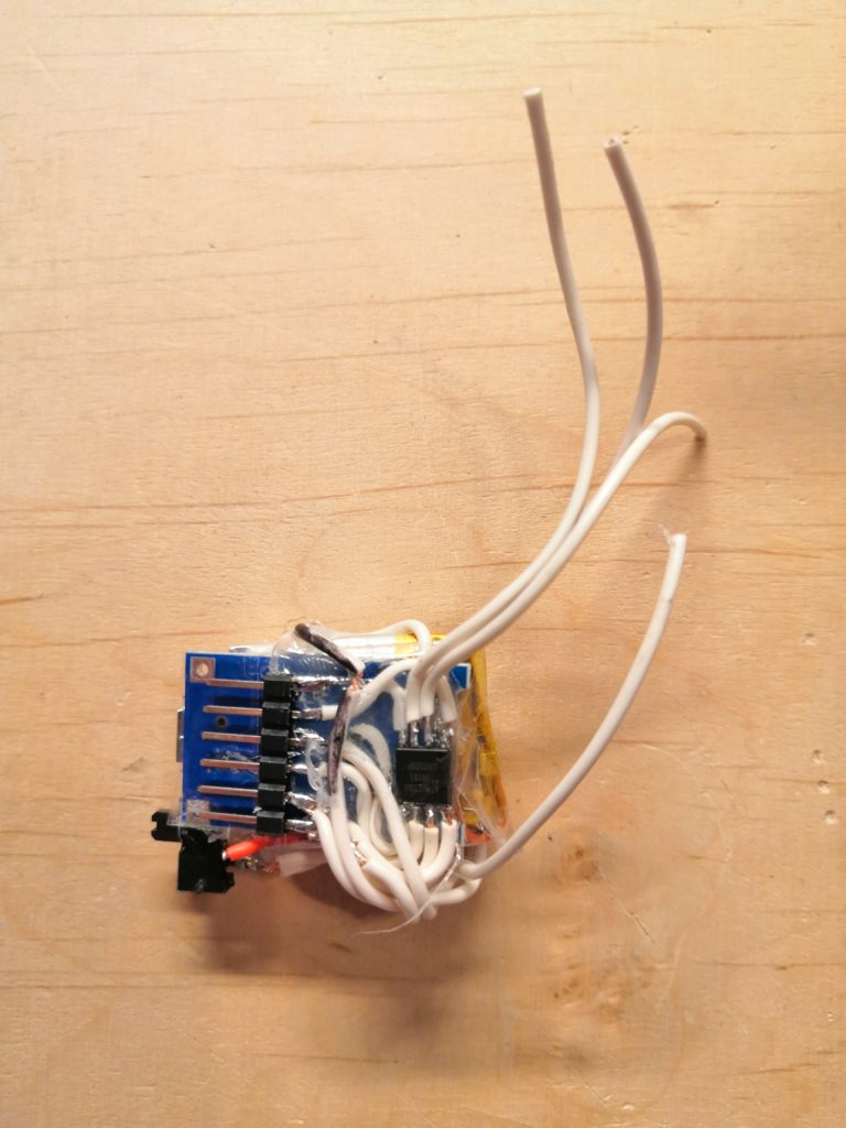
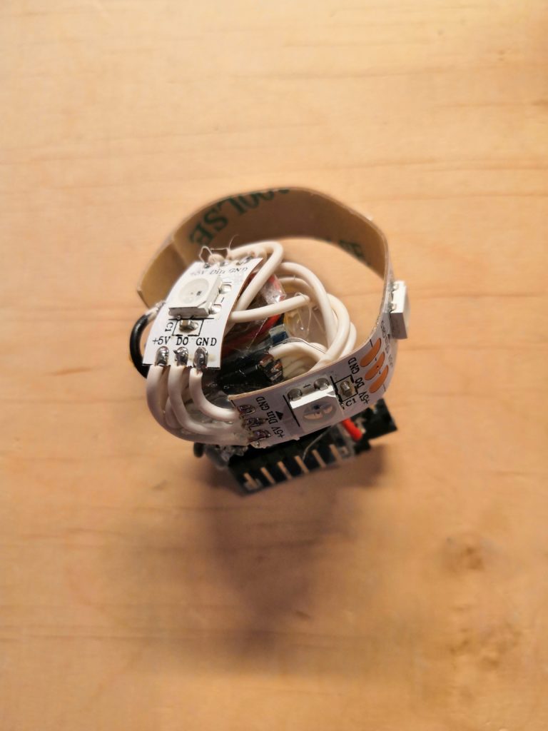
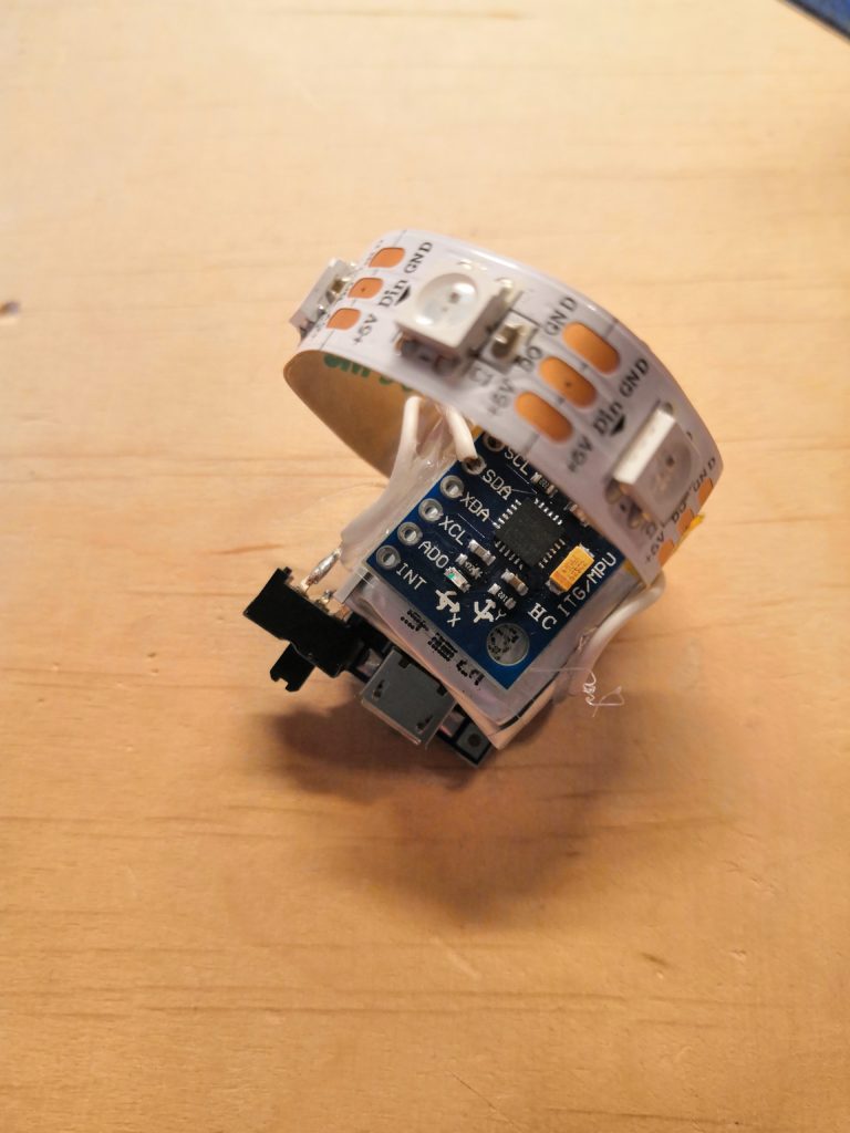
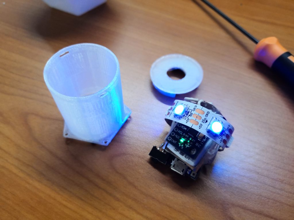
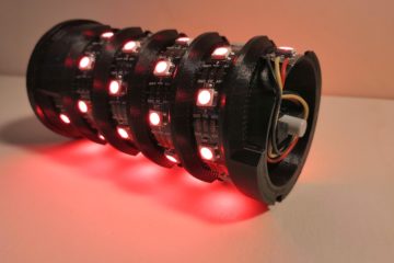
Here are some pictures how the electronic part looks like assembled:
Source code for the ATtiny85
As the source code for this project is minimal I will show it here in detail. I published the whole source code also on GitHub so that you can easily download it from there.
We start by importing the used libraries. I use the Adafruit_Neopixel library for controlling the LEDs. The TinyWireM is a really nice library to enable the I2C master interface on ATtiny microcontrollers, as the default Wire library from Arduino is not supported. As the third library, I import the math library to calculate the arctan from the equation above:
#include <Adafruit_NeoPixel.h>          // NeoPixel library used to run the NeoPixel LEDs
#include <TinyWireM.h>                  // I2C Master lib for ATTinys which use USI
#include <math.h>                       // math library to use math functions
I like to define some constants in the top of the code instead placing ‘magic numbers’ inside the code:
#define NEOPIXELPIN 4       // pin to which the NeoPixels are attached
#define NUMPIXELS 6         // number of pixels attached to Attiny85
#define MPU_ADDR 0x68       // I2C address of the MPU-6050. If AD0 pin is set to HIGH,
                            // the I2C address will be 0x69.
The next step is to define the global variables for sensor raw data. When we set up the NeoPixel library, we tell it how many pixels, and which pin to use to send signals. Note that for older NeoPixel strips you might need to change the third parameter — see the strandtest example from Adafruit for more information on possible values.
Adafruit_NeoPixel pixels = Adafruit_NeoPixel(NUMPIXELS, NEOPIXELPIN, NEO_GRB + NEO_KHZ800);

int16_t acc_x, acc_y, acc_z;      // variables for accelerometer raw data
int16_t gyro_x, gyro_y, gyro_z;   // variables for gyro raw data (optional)
int16_t temperature;              // variables for temperature data (optional)
I copied a very useful function from the strandtest example which is doing a mapping between a given value (0-255) and an RGB color value on the color wheel ( r -> g -> b back to r):
// Input a value 0 to 255 to get a color value.
// The colours are a transition r - g - b - back to r.
uint32_t Wheel(byte WheelPos) {
  WheelPos = 255 - WheelPos;
  if(WheelPos < 85) {
    return pixels.Color(255 - WheelPos * 3, 0, WheelPos * 3);
  }
  if(WheelPos < 170) {
    WheelPos -= 85;
    return pixels.Color(0, WheelPos * 3, 255 - WheelPos * 3);
  }
  WheelPos -= 170;
  return pixels.Color(WheelPos * 3, 255 - WheelPos * 3, 0);
}
The setup() function initializes the NeoPixels and wakes up the acceleration sensor MPU-6050.
void setup() {
  pixels.begin();             // This initializes the NeoPixel library.
  pixels.setBrightness(255);  // Set brightness of LEDs to 100%

  TinyWireM.begin();
  TinyWireM.beginTransmission(MPU_ADDR);  // Begins a transmission to the I2C slave (GY-521 board)
  TinyWireM.send(0x6B);                   // PWR_MGMT_1 register
  TinyWireM.send(0);                      // set to zero (wakes up the MPU-6050)
  TinyWireM.endTransmission(true);
}
In the loop() function we first send a request to the acceleration sensor. Followed by the code to receive and decoder the received data.
void loop() {

  TinyWireM.beginTransmission(MPU_ADDR);
  TinyWireM.send(0x3B);                   // starting with register 0x3B (ACCEL_XOUT_H)
  TinyWireM.endTransmission(false);
  TinyWireM.requestFrom(MPU_ADDR, 7*2);   // request a total of 7*2=14 registers

  // reading registers: 0x3B (ACCEL_XOUT_H) and 0x3C (ACCEL_XOUT_L)
  acc_x = TinyWireM.receive()<<8 | TinyWireM.receive();
  // reading registers: 0x3D (ACCEL_YOUT_H) and 0x3E (ACCEL_YOUT_L)
  acc_y = TinyWireM.receive()<<8 | TinyWireM.receive();
  // reading registers: 0x3F (ACCEL_ZOUT_H) and 0x40 (ACCEL_ZOUT_L)
  acc_z = TinyWireM.receive()<<8 | TinyWireM.receive();
  // reading registers: 0x41 (TEMP_OUT_H) and 0x42 (TEMP_OUT_L)
  temperature = TinyWireM.receive()<<8 | TinyWireM.receive();
  // reading registers: 0x43 (GYRO_XOUT_H) and 0x44 (GYRO_XOUT_L)
  gyro_x = TinyWireM.receive()<<8 | TinyWireM.receive();
  // reading registers: 0x45 (GYRO_YOUT_H) and 0x46 (GYRO_YOUT_L)
  gyro_y = TinyWireM.receive()<<8 | TinyWireM.receive();
  // reading registers: 0x47 (GYRO_ZOUT_H) and 0x48 (GYRO_ZOUT_L)
  gyro_z = TinyWireM.receive()<<8 | TinyWireM.receive();
Now we calculate the tilt angle as described in the formula at the top of this post:
double angle = atan(acc_y*1.0/acc_z) / M_PI * 180 + 90;
As last step we convert the angle to a color and set the color of the LEDs:
  // get pixel color from angle (mapping: angle -> colorwheel)
  uint32_t color = Wheel((int) (abs(angle*1.4)));

  // set all pixel to that color
  for(int i = 0; i < NUMPIXELS; i++){
    pixels.setPixelColor(i, color); // set color of pixel i
  }
  pixels.show(); // This sends the updated pixel color to the hardware.

  delay(100);
}
Flash the Attiny85
Now it is time to upload the code to the ATtiny microcontroller. Here I will show you shortly how to setup the Arduino IDE and how to get the program on the ATtiny:
- Connect the USBtinyISP to the Attiny85 and the computer. You may need to install the drivers for USBtinyISP first.
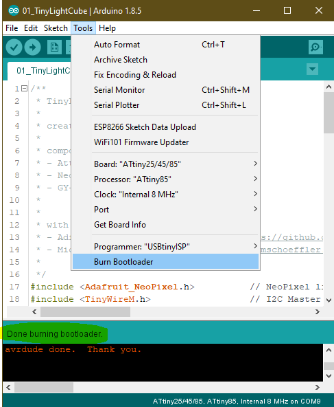
- Start the Arduino IDE. First, we have to make sure that we have installed the right board via the board manager. For the Attiny85 we have to install a package manually. You can find a good tutorial here on how to do it. As soon as the package is installed we need to set the right board settings (IDE -> Tools):
- Board: “ATtiny25/45/85”
- Processor: “ATtiny85”
- Clock: “Internal 8 MHz”
- Now we need to burn the bootloader. Select as Programmer ‘USBtinyISP’ and click then on ‘Burn bootloader’. If everything is working, it should end with a success message
- As mentioned above, I published the whole source code on GitHub. Download the source code and place it in your sketch folder. A little test helps to check if the configuration for the compiler is correct. To do this, compile the program with a click on ‘Verify’ without uploading.
- If compilation was successful we can upload the code to ATiny85 via ‘Sketch’ -> ‘Upload Using Programmer’.
3D printing the case
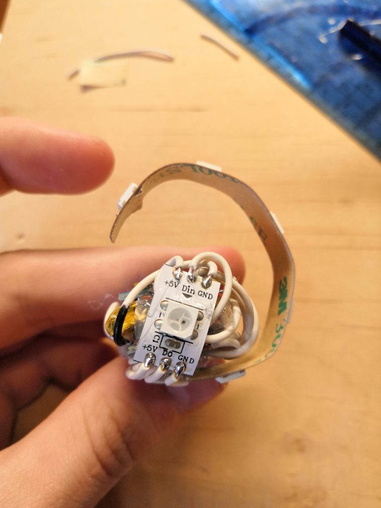
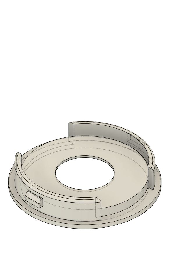
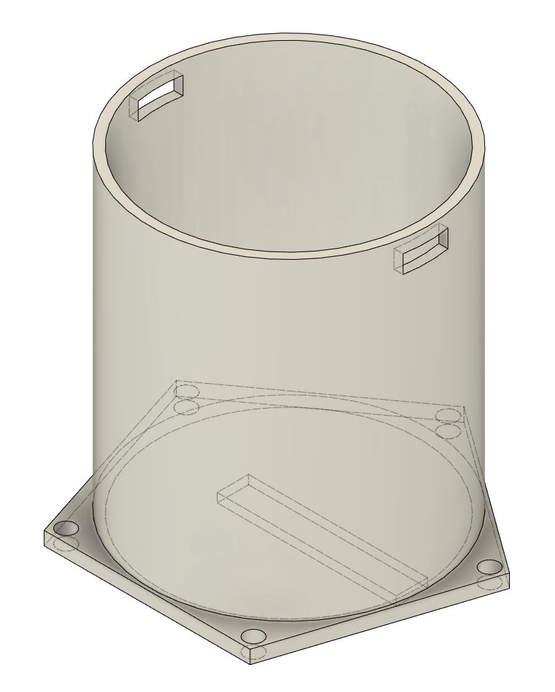
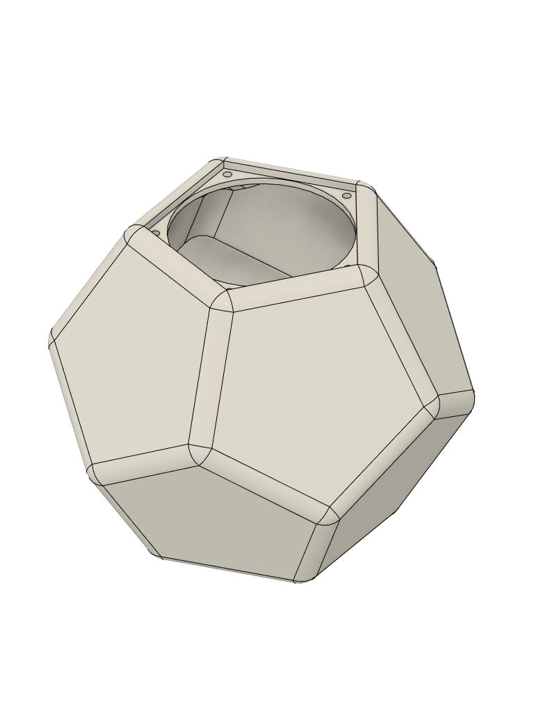
The semi-transparent case of the TinyLightCube consists of two layers. First, an inner cylinder, which holds the electronics and LEDs in place. This inner part is the same for all shapes (ball, cube, dodecahedron, …). On the outside, there is the second layer, which gives the TinyLightCube its shape.
Inner cylinder
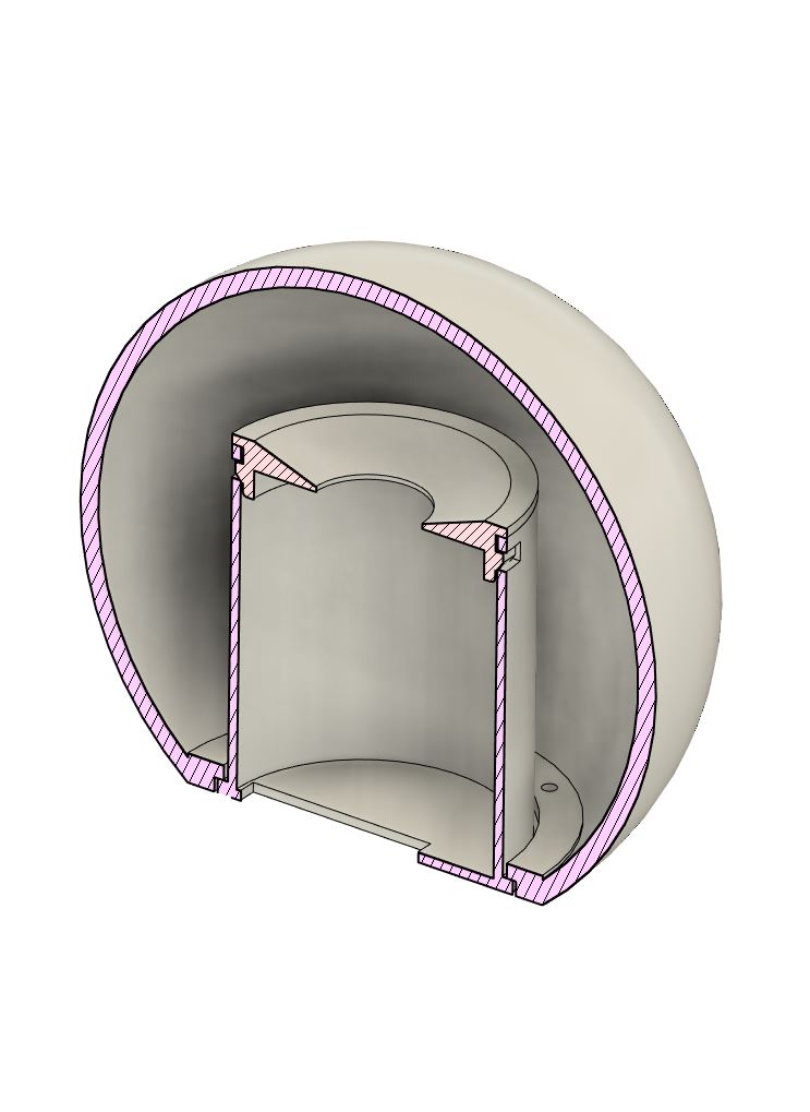
Outer shape
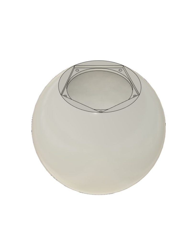
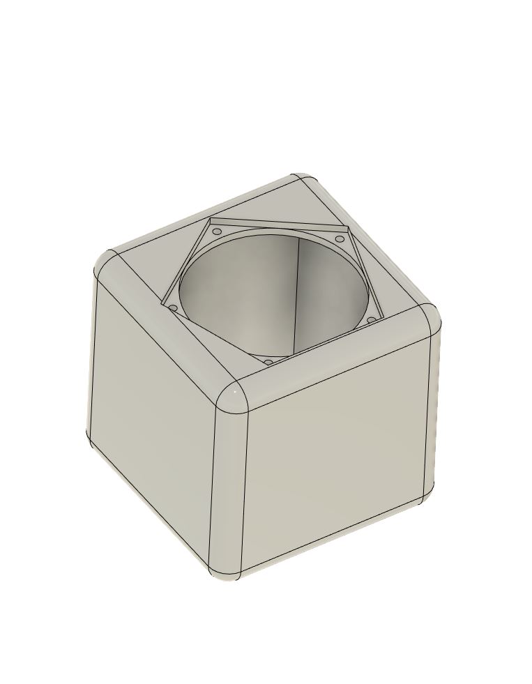
If you want to print the parts yourself, you can download the STL files also from the GitHub repository. I printed them in transparent PLA with 0.15 mm layer height, support, and 50% infill.
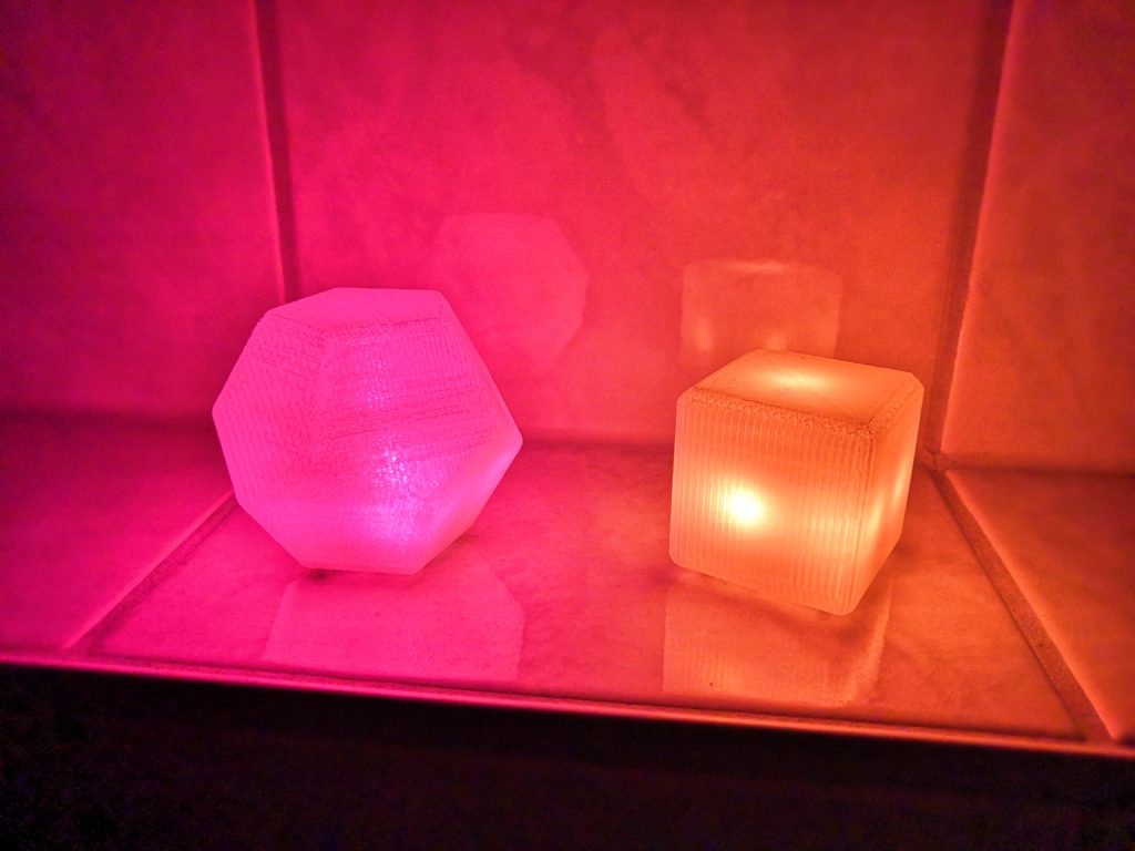
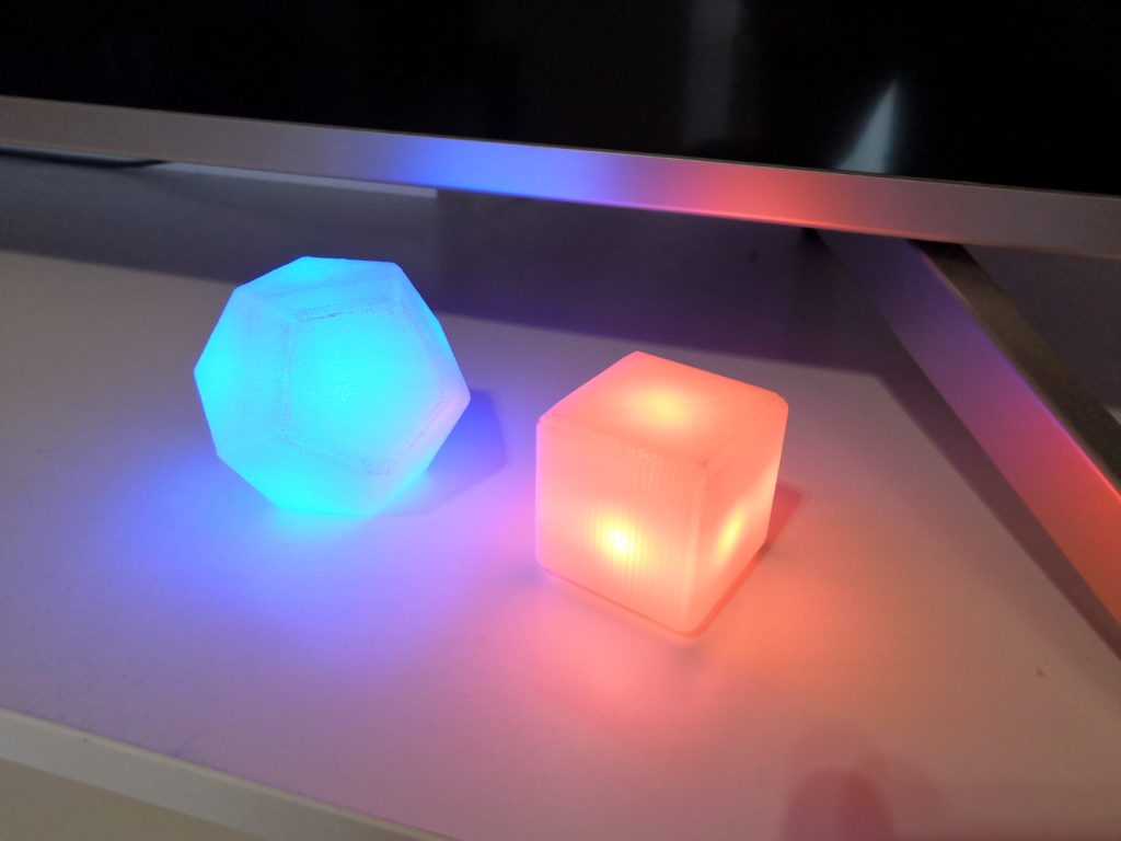
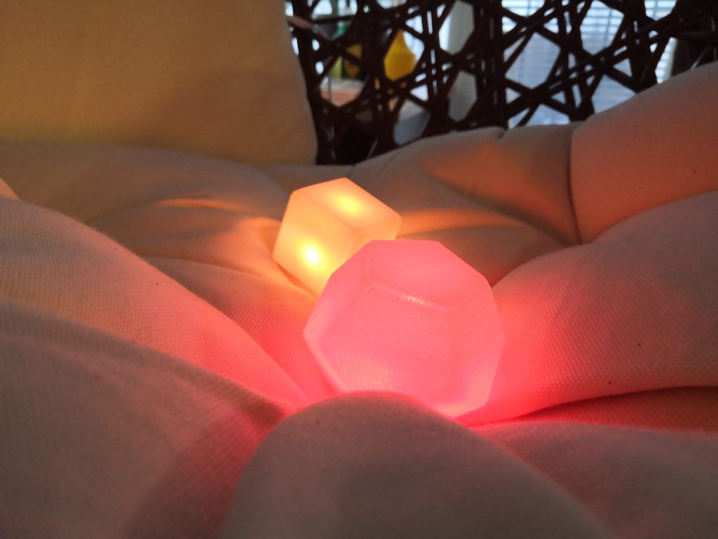
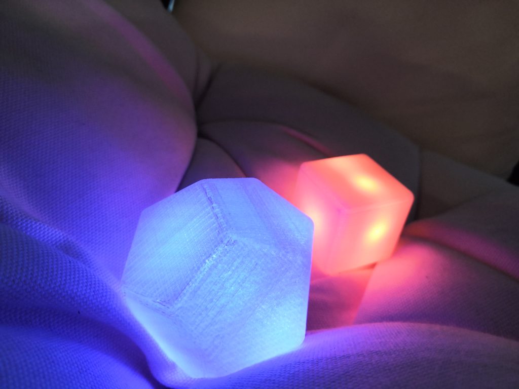
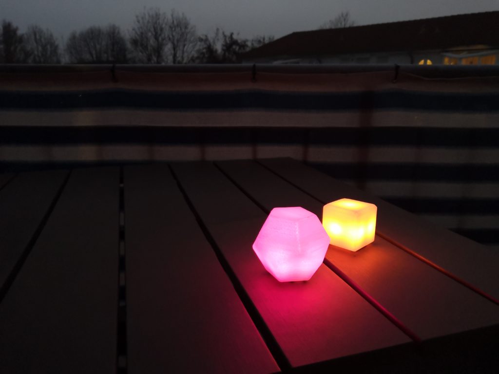
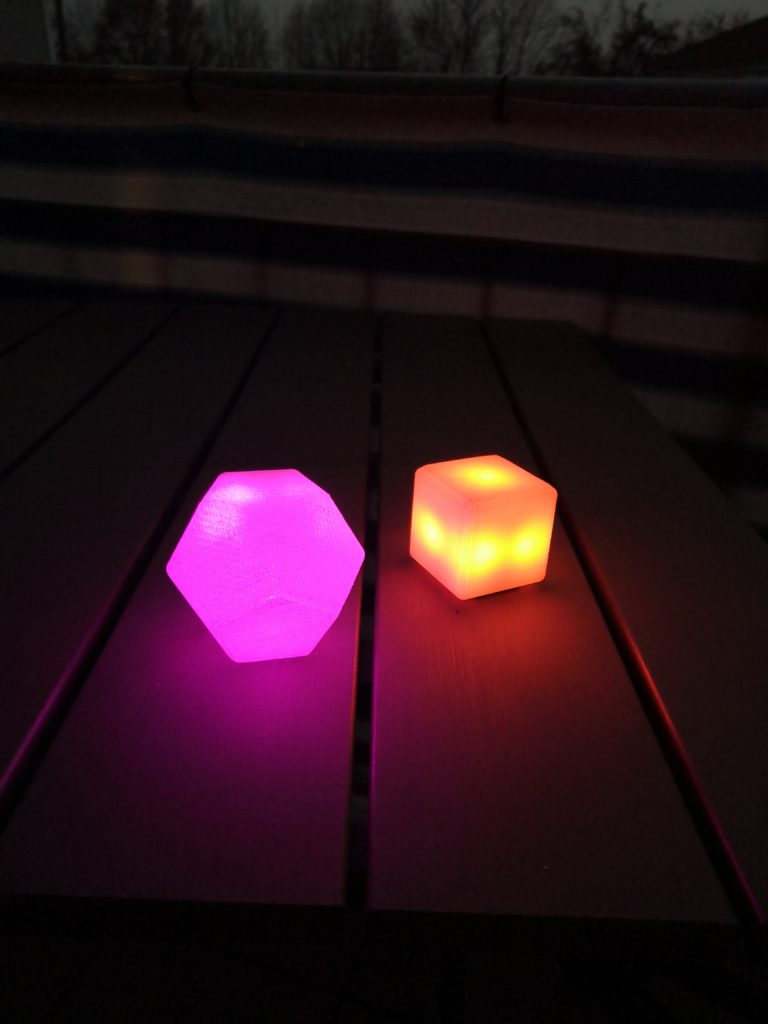
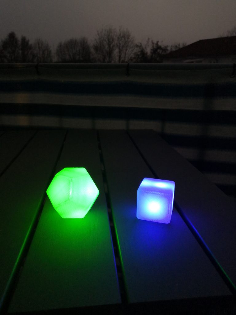
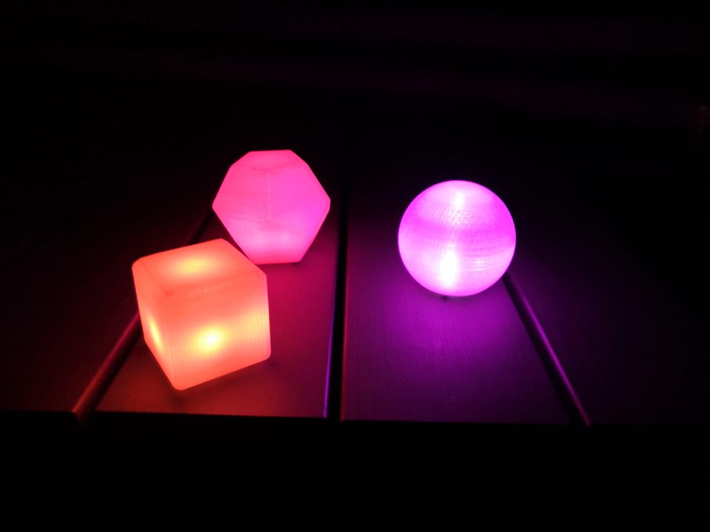
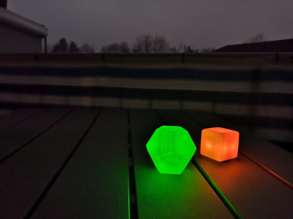
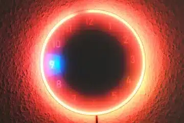
Photos of the LED light cubes
Here are some more images and videos of the LED light cubes in different environments:
0 Comments