The starting point of my new project was the fact that I bought my own small 3D printer and now thought about what I can build with this printer. It should be a complex mechanical project, but it should also be automated. I came up with the idea to build a 3D printed robot hand, which I wanted to control with servos.
By viewing the video, you agree that your data will be transmitted to YouTube and that you have read the privacy policy
Mechanical
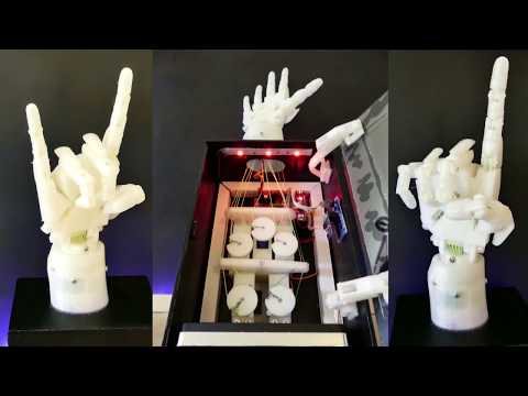
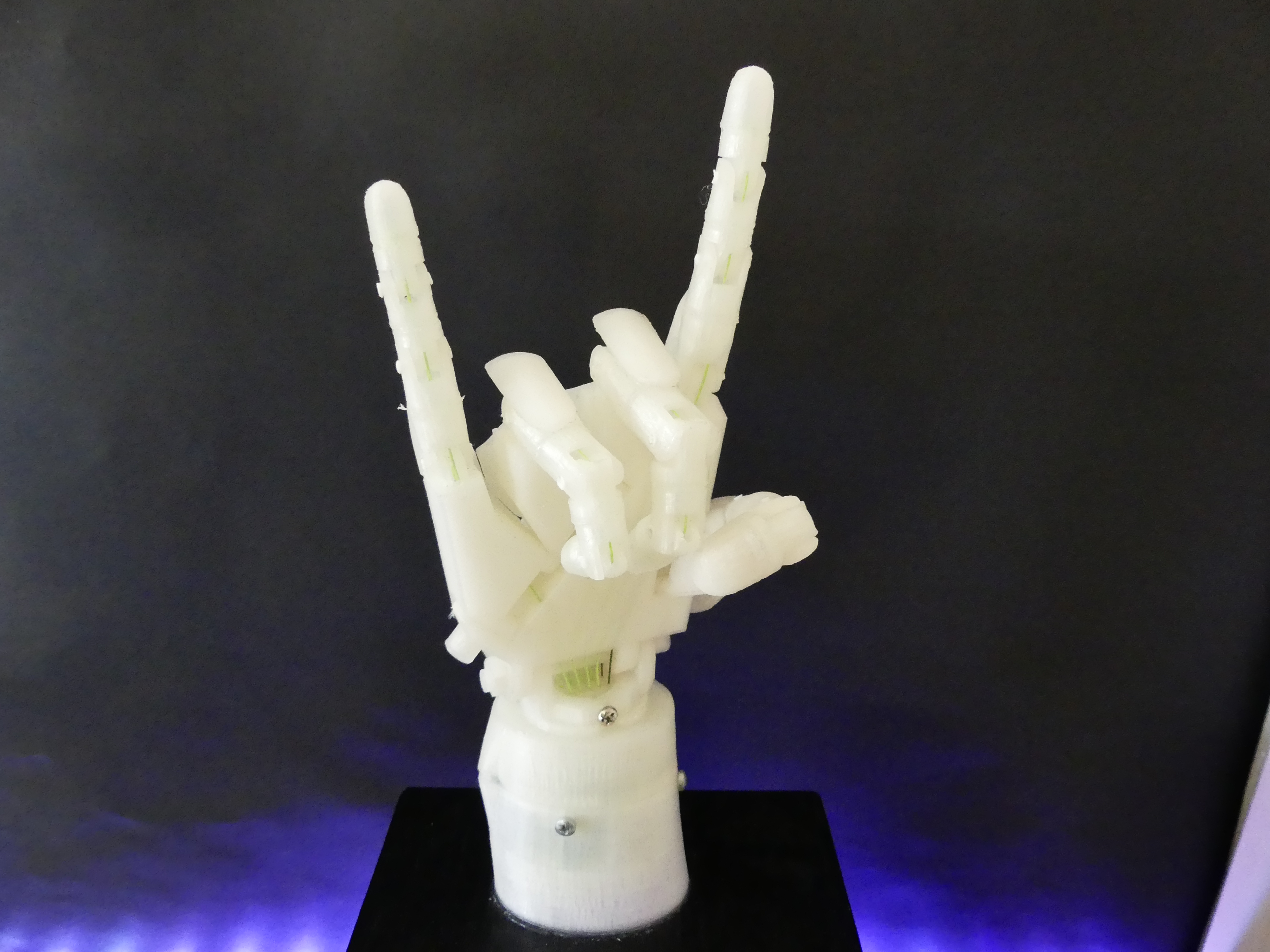
So I’m looking for a way how I can control each finger of the hand with a single servo. Finally, I came across the open-source project InMoov, which represents a 3D printed complete human-robot. There they use one servo per finger and control the fingers with two strings between each finger and servo. Since the project is open-source, you can download the individual CAD files of the hand and print them yourself. Unfortunately, my 3D printer is not big enough to print the hand in its original size, so I printed the hand in 80% of its size. Furthermore, I do not use the forearm to accommodate the servo, but I’ve built a small wooden black box for the servos, in which also the rest of the electronics accommodated.
The hand and the servo mounts consist of about 60 individual parts which I printed out before I started assembling the entire hand. For the finger joints, I used parts of the filament as a hinge pin because they had the correct diameter. I melted the ends of the filament a little with the soldering iron to prevent the joint from loosening again. I used a very tear-resistant fishing-line as tendons because it was recommended by the InMoov-Team.
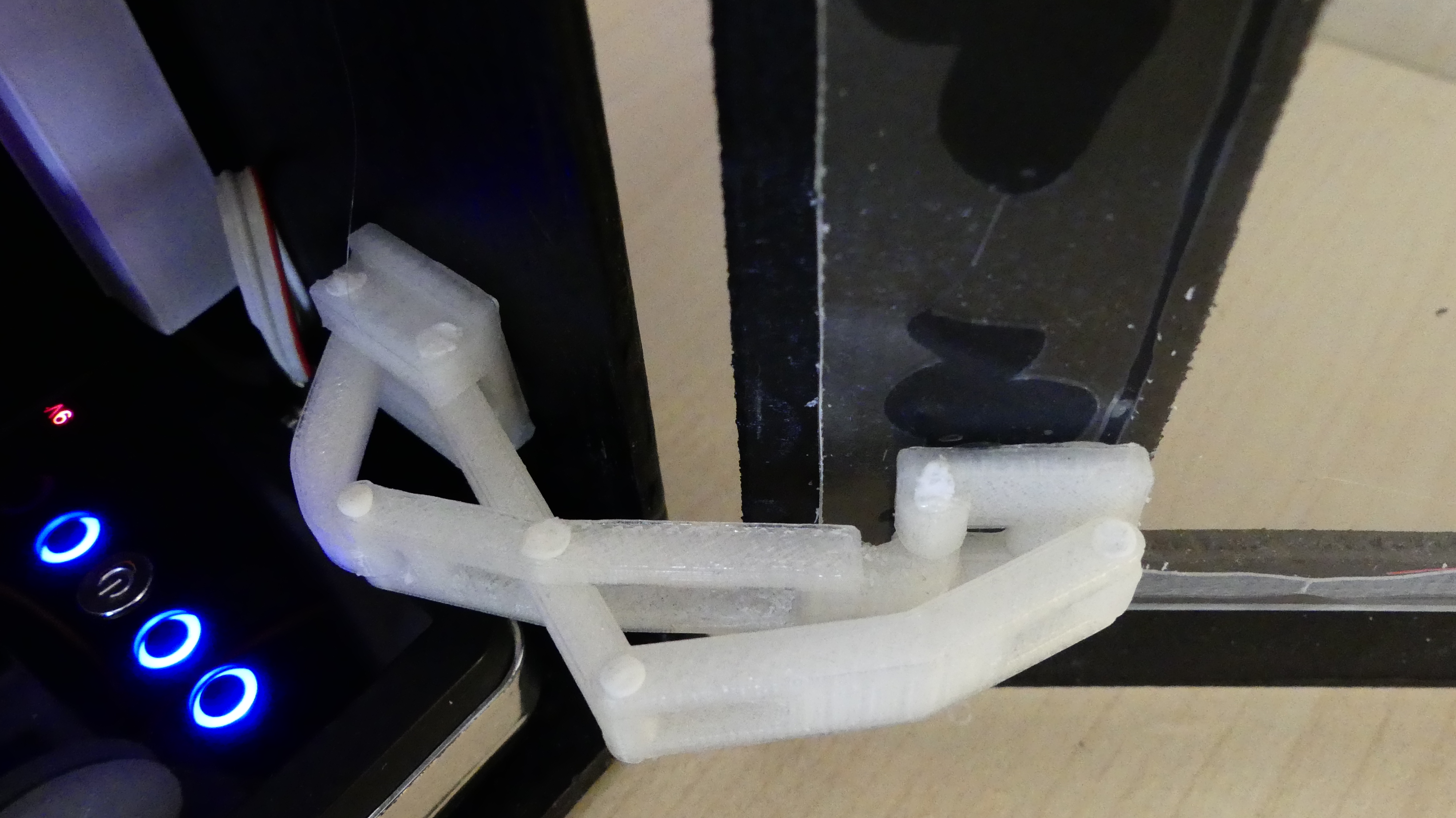
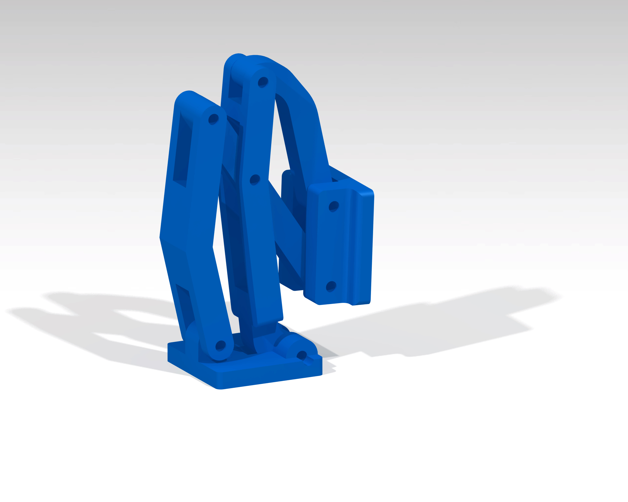
To be able to see the mechanical implementation with the servo in the box, I decided to place a window in the front of the box. For maintenance, I wanted to add an extra easy-to-open door. In order for the door to close properly, I did not have the right hinges so I constructed my own hinges from different templates and printed them with the 3D printer. The CAD files I have provided here.
Electrical
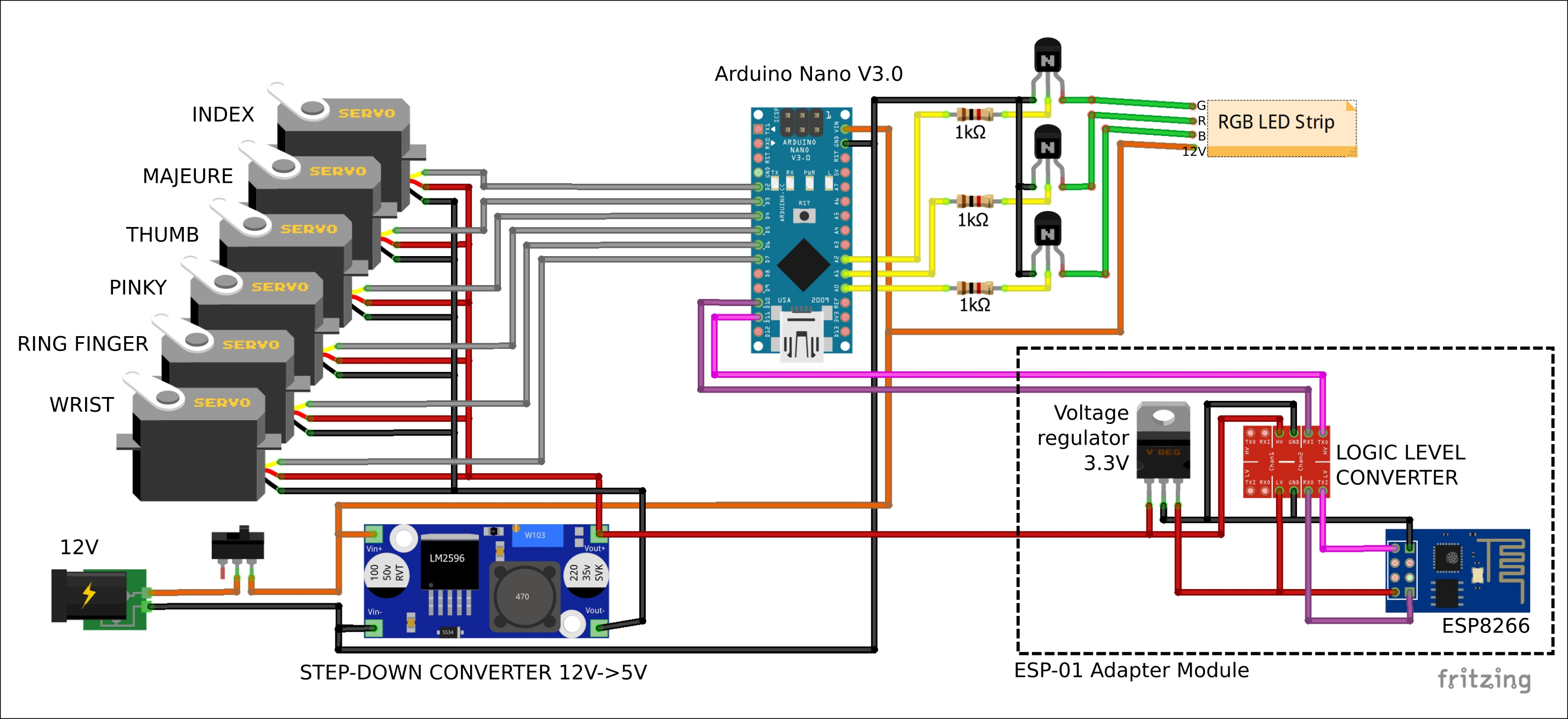
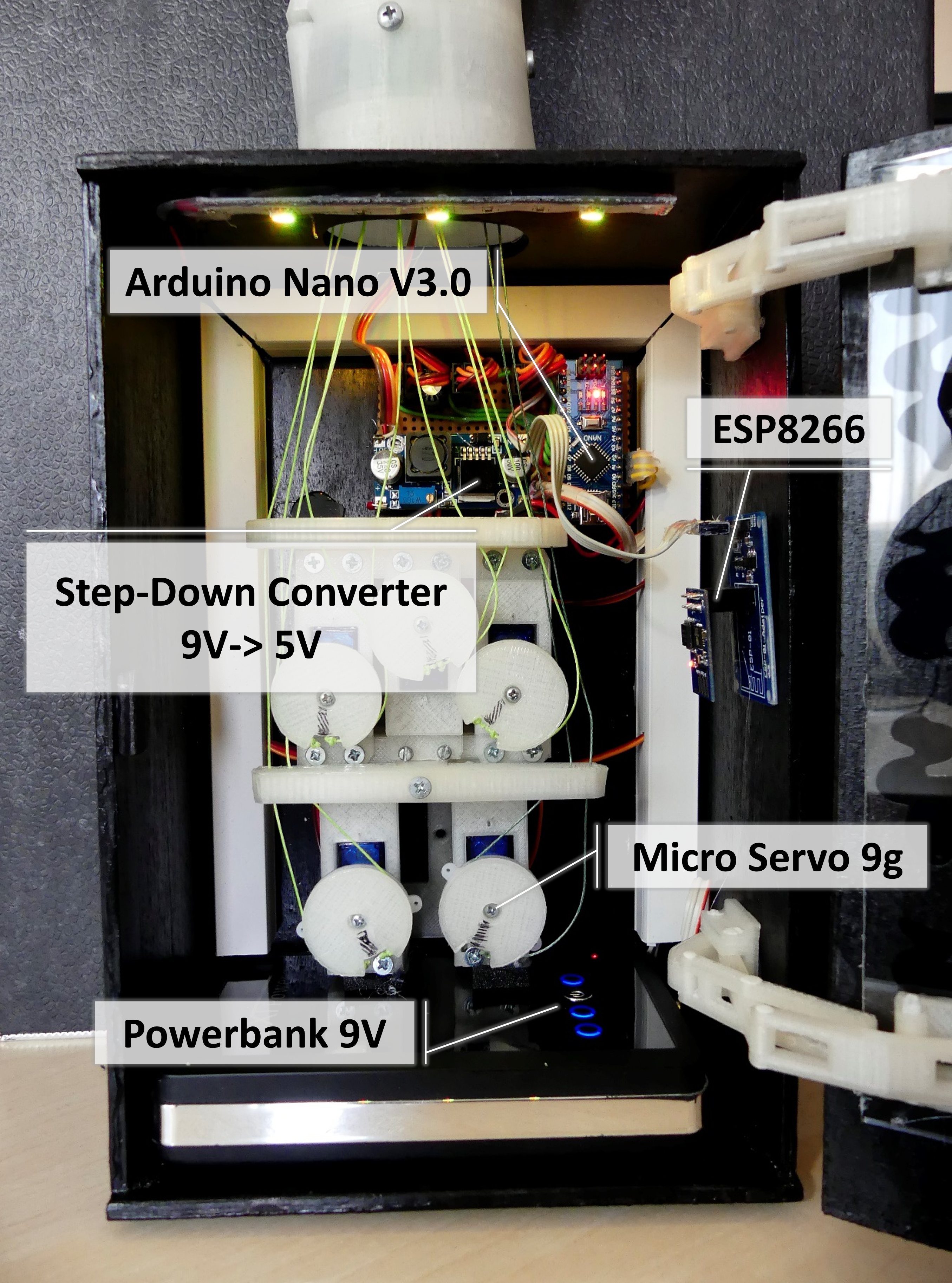
Each finger and the wrist is powered by a Micro Servo 9g with 5V. But since I only had a power bank with 9V, I need an additional step-down converter, which converts the voltage from 9V to 5V for the servos. With this 5V I operate also the WiFi module (ESP8266), on which a web server runs. The web server allows you to control the hand from any device, the ESP8266 has a serial connection to the Arduino Nano V3.0, which handles the actual control of the servo. In addition, I have implemented three RGB LEDs to illuminate the interior of the box, these are also controlled by the Arduino. Unfortunately, the servos and the WiFi module already occupy all PWM pins of the Arduino, so I can control the LEDs only via normal GPIOs.
Software
From a software point of view, I am currently only able to control the fingers and LEDs individually via the web server. However, I have already implemented the code for various gestures in the Arduino program, but the connection to the web server on the ESP8266 has not yet been made.
Furthermore, I have a TCP server as an alternative for the ESP8266 written to control the hand from any software on a computer. In the future, an optical gesture control will be implemented.
The entire source code is available on my GitHub repository.


0 Comments