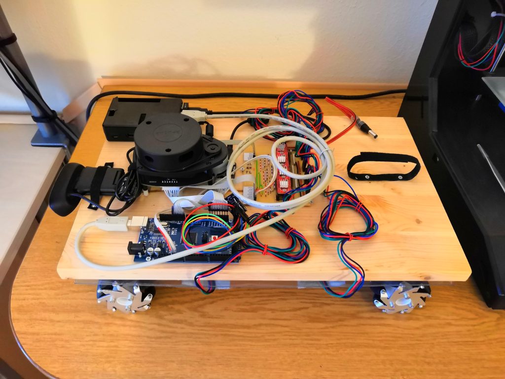
I started to build my first mobile robot with Mecanum Wheels a few weeks ago. In this post, I would like to show a look at the hardware structure. The software is an ongoing process and will be a topic in several future articles.
Parts for the mobile robot
I used the following parts to built my robot:
- 4x 60mm Mecanum Wheels
- 4x Stepper Motor Nema 17 Bipolar 59Ncm
- 4x Nema 17 Bracket for Stepper Motor
- 4x Stepper Driver A4988
- 1x Arduino Mega 2560
- 1x Raspberry Pi 3
- 1x RPLidar A1M8 – 360 Degree Laser Scanner Development Kit
- 1x Logitech C270 HD Webcam USB
- 1x Wooden Board 250 x 400 x 20 mm
- 1x Plastic Board 250 x 400 x 3 mm
- some cables, connectors, nuts, and screws
Motors and Wheels
My initial idea was to use four 12V DC motors with attached encoders, as I’ve seen in other videos about self-built mobile robots. However, when I saw the price of such a DC motor with encoder, I looked for an alternative.
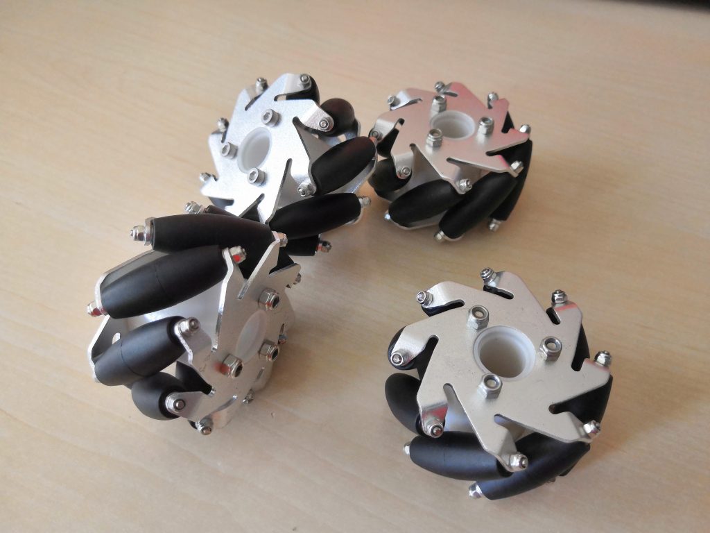
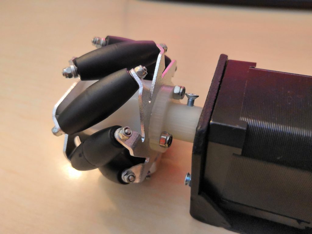
For the coupling between the motor and the Mecanum Wheel, the Mecanum Wheel dealer offers the appropriate adapter hubs, but these do not fit on the motor shafts of the stepper motors. So I designed them myself and printed them out on the 3D printer.
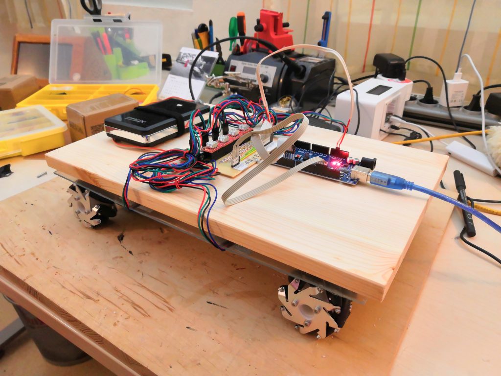
The base of the mobile robot
My first design for the base of the robot was to use a simple wooden board. On this board I screw the motors with their brackets directly against it from below. After I had mounted the motors and wheels, however, I noticed that the robot was too stiff and not all four wheels touched the ground. However, for the Mecanum Wheels to function properly, all four wheels must always be in contact with the ground.
So I had to think about an alternative suspension that would guarantee that all the wheels would always press on the ground. My current solution (certainly not the best) is to use an elastic plastic plate as an intermediate layer to which the motors are attached. The intermediate layer is only connected to the stiff wooden board at four points and allows the motor or wheels to adapt individually to the ground.
Update Feb 2019: The suspension with this intermediate layer was only a temporary solution. I have now developed an improved solution which I would like to introduce briefly. The aim is an independent wheel suspension with real steel springs. They offer longer durability and stability than the intermediate layer. It took a little trial and error until I finally came up with the solution shown in the following picture. Each wheel has a single spring and a hinge that holds a small wooden board in a fixed position. The stepper motor is then mounted on this wooden board.
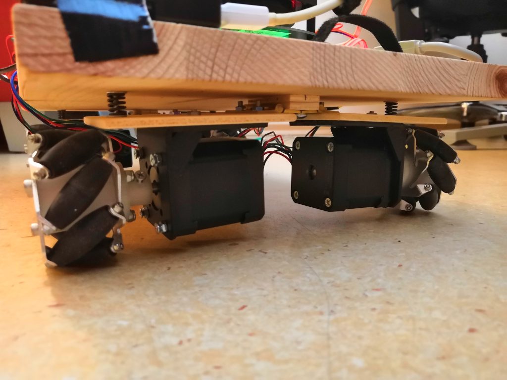

improved suspension 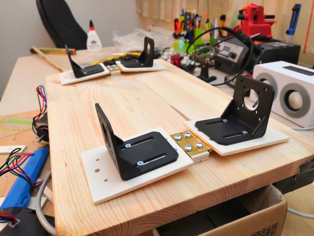
improved suspension under construction (upside down)
Motorcontrol
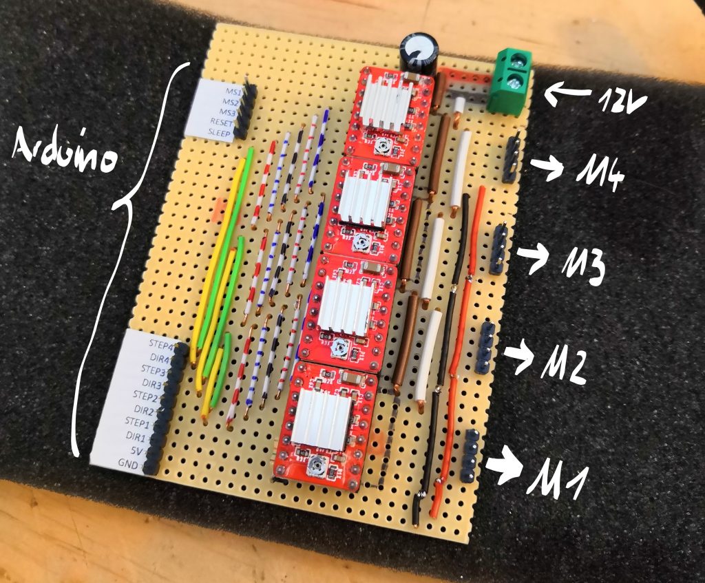
I have never worked with stepper motors before, so I had to inform myself about their control. With the help of special stepper motor drivers, like the A4988, this is really a piece of cake. All I need is a microcontroller with which I can send the direction of rotation and the clock rate as discrete pin signals to the motor drivers. Each motor has its own motor driver. The circuit diagram for the control of a motor looks like this:
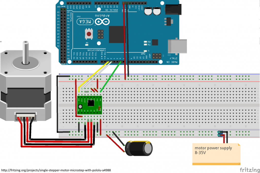
I use an Arduino Mega 2560 as microcontroller, which is a bit oversized for the current state of the robot, but maybe I’ll build more functions on my robot in the future, so I’m happy about the many pins of the Mega.
Power supply
The power supply is currently still a simple power bank with 12V output voltage. For the first tests this is good, I will have to replace it with something bigger in the future, because the maximum output current is only 2A right now.
The Brain: Raspberry Pi 3
At least a small brain :). I already made the plan at the beginning of the project, that all calculations for the operation of the robot are carried out on an external, powerful computer. Only a small computer unit is working on the robot itself, which provides all sensor signals via TCP servers and transmits the motor commands to the Arduino.
My first choice was a Raspberry Pi Zero
Laserscanner and camera
For the moment, I have decided to use only an RPLIDAR 360° laser scanner and a simple webcam as sensors. I simply connected the laser scanner and the webcam to the Raspberry Pi via USB. I’m not sure yet about the exact positioning of the two devices.
Furthermore I will add a MPU-9250 as IMU, which is connected to the Arduino via SPI.

0 Comments