With this post, I want to start with the description of the software for my mobile robot. One of the first things I’m setting up in the software is an OTA (Over the Air) update function for all my components on the robot. That means besides the Raspberry Pi, I want to flash the Arduino Mega as well as the Attiny from my external PC with new software. As soon as I have written a new program in the Arduino IDE for the Arduino or Attiny, the code should be uploaded directly to the corresponding controller by clicking on ‘Upload’. And that without the need to plug in a cable connection first. In this post, I show how I implement this functionality.
Architecture
A look at the architecture shows that the task definition includes four components and three communication lines.
components:
- External Linux Workstation
- Raspberry Pi
- Arduino Mega 2560
- Attiny84
communication lines:
- Linux PC -> Raspberry Pi: WLAN (Ethernet)
- Raspberry Pi -> Arduino Mega: USB (serial)
- Raspberry Pi -> Attiny84: SPI
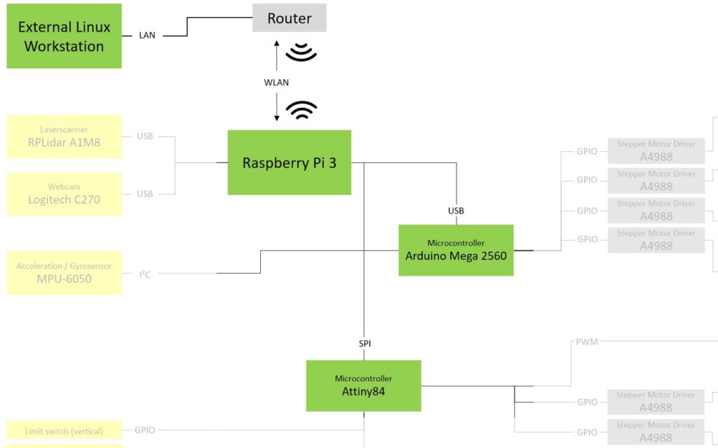
Find the whole Architecture in my previous post.
Flashing with Arduino IDE in general
Before we look at the individual components and communication lines, I would like to briefly describe the update process at Arduino in general:
- step: Board-Settings
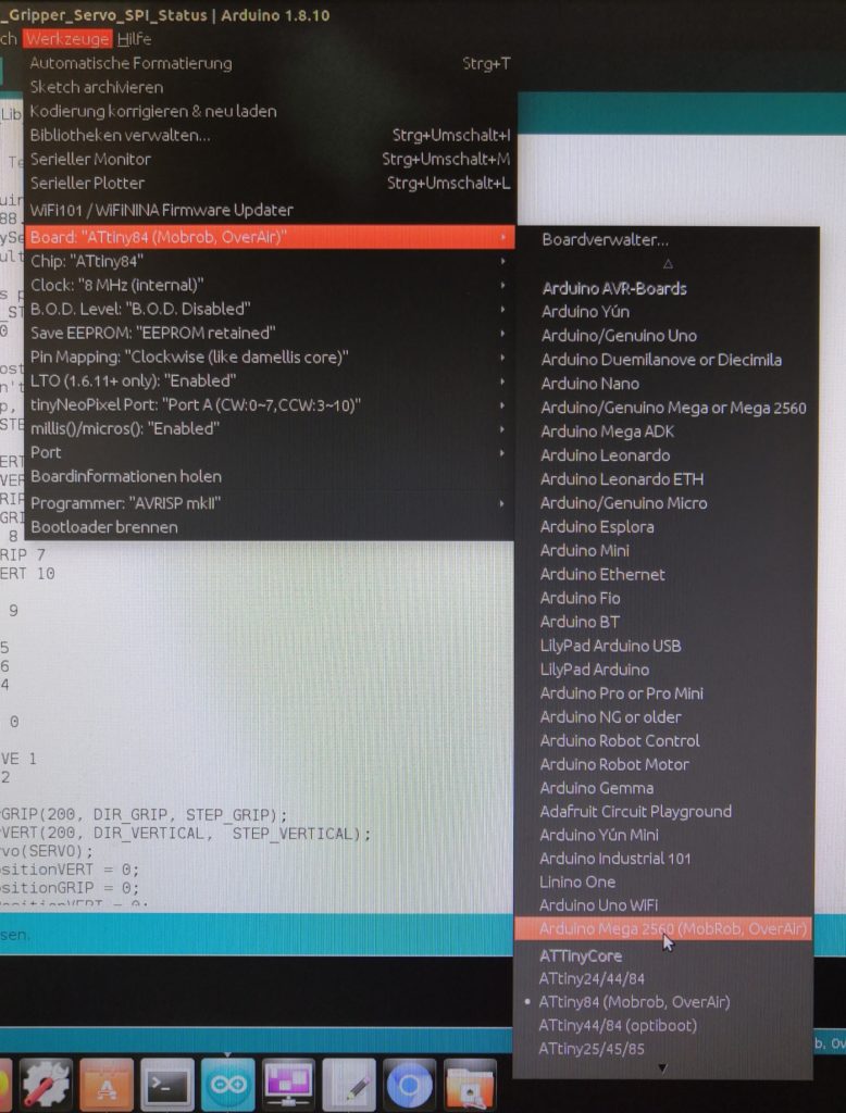
Once you have finished writing your code in the Arduino IDE, you usually select a specific board from the ‘Tools’ menu. By selecting this board, the IDE knows which parameters to pass to the compiler when compiling your code. - step: Compiler
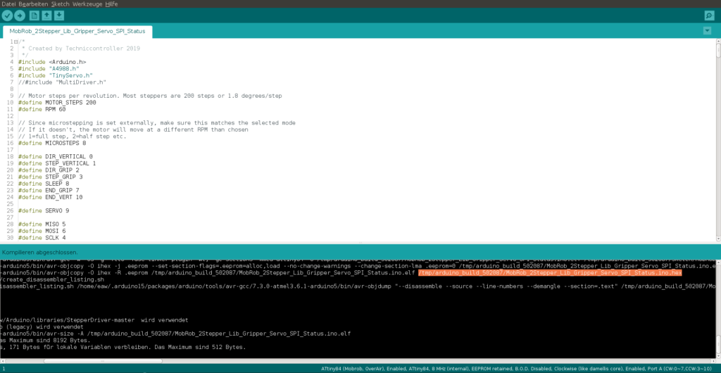
By clicking ‘Upload’ the Arduino IDE starts the compiler with the above-mentioned parameters. The compiler converts the written C++ code (.ino file) into binary machine code. One result of this step is a .hex file. You can also see this if you have activated verbose output in the Arduino IDE under Preferences:
- step: Upload
If you have enabled verbose output for upload as well, you can see that the Arduino IDE calls the avrdude tool with some parameters after compilation. One parameter is the COM port and the path of the mentioned .hex file. Afterward, the upload of the code to the USB connected board starts.
The idea of the OTA update is not to load the .hex file created on my Linux PC directly onto a board using avrdude. Instead, send the .hex file to the Raspberry Pi via WLAN. On the Raspberry Pi, the tool avrdude should then continue with the transfer to the board.
Send the .hex file to the Raspberry Pi
Sending the hex file to Raspberry Pi is divided into three blocks.
- To write an own transfer program on the Linux PC which sends the .hex file to the Raspberry Pi
- Get Arduino IDE to start my own transfer program instead of avrdude after compiling
- Write a program on the Raspberry Pi which receives the file and triggers a call of avrdude.
1. Own transfer program
First of all, we create our transfer program. To accomplish this task it is sufficient to write a few lines of the python script send2Pi.py:
#!/usr/bin/python
# -*- coding: utf-8 -*-
"""
send2Pi.py

Created on Sat Apr 27 13:12:21 2019

@author: Techniccontroller
"""
import requests
import sys, getopt

def main(argv):
    try:
        opts, args = getopt.getopt(argv,"hu:f:",["url=","hexfile="])
    except getopt.GetoptError:
        print('GetoptError: send2Pi -u <url> -f <hexfile>')
        sys.exit(2)

    # extract url and path from parameters
    for opt, arg in opts:
        if opt == '-h':
            print('send2Pi -u <url> -f <hexfile>')
            sys.exit()
        elif opt in ("-u", "--url"):
            url = arg
        elif opt in ("-f", "--hexfile"):
            hexfile = arg.strip()
    print("url:" + str(url))
    print("hexfile:" + str(hexfile))
    print("uploading ...")

    # extract filename
    folders = hexfile.split("/")
    filename = folders[-1]

    #read file from filesystem
    data = open(hexfile, 'rb')

    # set header
    headers = {'filename': filename}

    # send file
    r = requests.post(url, data=data, headers=headers)

    print(r.text)

if __name__ == "__main__":
   main(sys.argv[1:])
To get an executable application we pack the file send2Pi.py with pyinstaller. We execute the following command in the directory where we have stored the Python script:
pyinstaller -F send2Pi.py
The command creates a folder dist in which the executable application can be found. In my case the complete path to the application is /home/eaw/UpdateOverAir/dist/send2Pi. This command works the same way for Windows users.
2. Configuring the Arduino IDE
First, we have to make sure that we have installed the right board via the board manager. The Arduino Mega is pre-installed by default. For the Attiny84 we have to install a package manually. You can find a good tutorial here. As soon as the boards are installed a little test helps to check if the configuration for the compiler is correct. To do this, compile the code with a click on ‘Verify’ without uploading. Now let’s configure the Arduino IDE to call our transfer program send2Pi instead of avrdude after compilation.
Attiny84: First we change to the directory ~/.arduino15/packages/ATTinyCore/hardware/avr/1.3.3 and open the file platform.txt. This file defines the compilers and uploaders used by the Arduino IDE. Therefore we add the following lines to the end of the file:
(...)

# Custom upload tools
# ------------------------------

tools.overair.path={runtime.tools.avrdude.path}
tools.overair.cmd.path=/home/eaw/UpdateOverAir/dist/send2Pi
tools.overair.config.path={path}/etc/avrdude.conf

tools.overair.upload.params.verbose=-v
tools.overair.upload.params.quiet=-q -q
tools.overair.upload.verify=
tools.overair.upload.params.noverify=-V
tools.overair.upload.pattern="{cmd.path}" "-u {upload.url}" "-f {build.path}/{build.project_name}.hex"
Please note that the path to application may be different for you.
The second file we need to change is also in the directory ~/.arduino15/packages/ATTinyCore/hardware/avr/1.3.3 and is called boards.txt. Here are all boards defined which are available in the package ATTinyCore. So we copy the lines for an existing board (in my case ATtiny24/44/84) and adjust the marked entries. You need to insert the hostname of the Raspberry Pi into the upload URL, in my case the hostname is mobrob.
(...)

tinymobrob.name=ATtiny84 (Mobrob, OverAir)
tinymobrob.bootloader.tool=avrdude
tinymobrob.bootloader.unlock_bits=0xff
tinymobrob.bootloader.lock_bits=0xff
tinymobrob.build.core=tiny
tinymobrob.build.board=AVR_ATTINYX4
tinymobrob.upload.tool=overair
tinymobrob.build.board=AVR_ATTINYX4
tinymobrob.bootloader.tool=avrdude
tinymobrob.bootloader.unlock_bits=0xFF
tinymobrob.bootloader.lock_bits=0xFF
tinymobrob.bootloader.file=empty/empty_all.hex
tinymobrob.menu.LTO.enable=Enabled
tinymobrob.menu.LTO.enable.ltocflags=-flto -fno-fat-lto-objects
tinymobrob.menu.LTO.enable.ltoelfflags=-g -flto -fuse-linker-plugin
tinymobrob.menu.LTO.enable.ltocppflags=-flto
tinymobrob.menu.LTO.enable.ltoarcmd=gcc-
tinymobrob.menu.LTO.disable=Disabled
tinymobrob.menu.LTO.disable.ltocflags=
tinymobrob.menu.LTO.disable.ltoelfflags=
tinymobrob.menu.LTO.disable.ltocppflags=
tinymobrob.menu.LTO.disable.ltoarcmd=
tinymobrob.menu.chip.84=ATtiny84
tinymobrob.menu.chip.84.build.mcu=attiny84
tinymobrob.menu.chip.84.upload.protocol=wiring
tinymobrob.menu.chip.84.upload.maximum_size=8192
tinymobrob.menu.chip.84.upload.maximum_data_size=512
tinymobrob.menu.chip.84.upload.speed=19200
tinymobrob.menu.chip.84.upload.url=http://mobrob:8080/postAttinyISPCode
tinymobrob.menu.chip.44=ATtiny44
tinymobrob.menu.chip.44.build.mcu=attiny44
tinymobrob.menu.chip.44.upload.maximum_size=4096
tinymobrob.menu.chip.44.upload.maximum_data_size=256
tinymobrob.menu.chip.24=ATtiny24
tinymobrob.menu.chip.24.build.mcu=attiny24
tinymobrob.menu.chip.24.upload.maximum_size=2048
tinymobrob.menu.chip.24.upload.maximum_data_size=128
tinymobrob.build.core=tiny
tinymobrob.build.export_merged_output=false
tinymobrob.bootloader.extended_fuses=0xFF
tinymobrob.menu.clock.8internal=8 MHz (internal)
tinymobrob.menu.clock.8internal.bootloader.low_fuses=0xE2
tinymobrob.menu.clock.8internal.build.f_cpu=8000000L
tinymobrob.menu.clock.8internal.build.clocksource=0
tinymobrob.menu.clock.20external=20 MHz (external)
tinymobrob.menu.clock.20external.bootloader.low_fuses=0xFF
tinymobrob.menu.clock.20external.build.f_cpu=20000000L
tinymobrob.menu.clock.20external.build.clocksource=1
tinymobrob.menu.clock.16external=16 MHz (external)
tinymobrob.menu.clock.16external.bootloader.low_fuses=0xFF
tinymobrob.menu.clock.16external.build.f_cpu=16000000L
tinymobrob.menu.clock.16external.build.clocksource=1
tinymobrob.menu.clock.12external=12 MHz (external)
tinymobrob.menu.clock.12external.bootloader.low_fuses=0xFF
tinymobrob.menu.clock.12external.build.f_cpu=12000000L
tinymobrob.menu.clock.12external.build.clocksource=1
tinymobrob.menu.clock.8external=8 MHz (external)
tinymobrob.menu.clock.8external.bootloader.low_fuses=0xFF
tinymobrob.menu.clock.8external.build.f_cpu=8000000L
tinymobrob.menu.clock.8external.build.clocksource=1
tinymobrob.menu.clock.6external=6 MHz (external)
tinymobrob.menu.clock.6external.bootloader.low_fuses=0xFD
tinymobrob.menu.clock.6external.build.f_cpu=6000000L
tinymobrob.menu.clock.6external.build.clocksource=1
tinymobrob.menu.clock.4external=4 MHz (external)
tinymobrob.menu.clock.4external.bootloader.low_fuses=0xFD
tinymobrob.menu.clock.4external.build.f_cpu=4000000L
tinymobrob.menu.clock.4external.build.clocksource=1
tinymobrob.menu.clock.1internal=1 MHz (internal)
tinymobrob.menu.clock.1internal.bootloader.low_fuses=0x62
tinymobrob.menu.clock.1internal.build.f_cpu=1000000L
tinymobrob.menu.clock.1internal.build.clocksource=0
tinymobrob.menu.clock.737external=7.372 MHz (external)
tinymobrob.menu.clock.737external.bootloader.low_fuses=0xFD
tinymobrob.menu.clock.737external.build.f_cpu=7372800L
tinymobrob.menu.clock.737external.build.clocksource=1
tinymobrob.menu.clock.92external=9.216 MHz (external)
tinymobrob.menu.clock.92external.bootloader.low_fuses=0xFF
tinymobrob.menu.clock.92external.build.f_cpu=9216000L
tinymobrob.menu.clock.92external.build.clocksource=1
tinymobrob.menu.clock.11external=11.0592 MHz (external)
tinymobrob.menu.clock.11external.bootloader.low_fuses=0xFF
tinymobrob.menu.clock.11external.build.f_cpu=11059200L
tinymobrob.menu.clock.11external.build.clocksource=1
tinymobrob.menu.clock.14external=14.7456 MHz (external)
tinymobrob.menu.clock.14external.bootloader.low_fuses=0xFF
tinymobrob.menu.clock.14external.build.f_cpu=14745600L
tinymobrob.menu.clock.14external.build.clocksource=1
tinymobrob.menu.clock.184external=18.432 MHz (external)
tinymobrob.menu.clock.184external.bootloader.low_fuses=0xFF
tinymobrob.menu.clock.184external.build.f_cpu=18432000L
tinymobrob.menu.clock.184external.build.clocksource=1
tinymobrob.menu.clock.4internal=4 MHz (internal)
tinymobrob.menu.clock.4internal.bootloader.low_fuses=0x62
tinymobrob.menu.clock.4internal.build.f_cpu=4000000L
tinymobrob.menu.clock.4internal.build.clocksource=0
tinymobrob.menu.clock.128internal=128 kHz (internal WDT)
tinymobrob.menu.clock.128internal.bootloader.low_fuses=0xC4
tinymobrob.menu.clock.128internal.build.f_cpu=128000L
tinymobrob.menu.clock.128internal.build.clocksource=3
tinymobrob.bootloader.high_fuses=0b1101{bootloader.eesave_bit}{bootloader.bod_bits}
tinymobrob.menu.eesave.aenable=EEPROM retained
tinymobrob.menu.eesave.aenable.bootloader.eesave_bit=0
tinymobrob.menu.eesave.disable=EEPROM not retained
tinymobrob.menu.eesave.disable.bootloader.eesave_bit=1
tinymobrob.menu.bod.disable=B.O.D. Disabled
tinymobrob.menu.bod.disable.bootloader.bod_bits=111
tinymobrob.menu.bod.1v8=B.O.D. Enabled (1.8v)
tinymobrob.menu.bod.1v8.bootloader.bod_bits=110
tinymobrob.menu.bod.2v7=B.O.D. Enabled (2.7v)
tinymobrob.menu.bod.2v7.bootloader.bod_bits=101
tinymobrob.menu.bod.4v3=B.O.D. Enabled (4.3v)
tinymobrob.menu.bod.4v3.bootloader.bod_bits=100
tinymobrob.menu.pinmapping.anew=Clockwise (like damellis core)
tinymobrob.menu.pinmapping.anew.build.variant=tinyX4_reverse
tinymobrob.menu.pinmapping.old=Counterclockwise (like old ATTinyCore and x41-series)
tinymobrob.menu.pinmapping.old.build.variant=tinyX4
tinymobrob.menu.millis.enabled=Enabled
tinymobrob.menu.millis.disabled=Disabled (saves flash)
tinymobrob.menu.millis.enabled.build.millis=
tinymobrob.menu.millis.disabled.build.millis=-DDISABLEMILLIS
tinymobrob.menu.neopixelport.porta=Port A (CW:0~7,CCW:3~10)
tinymobrob.menu.neopixelport.portb=Port A (CW:8~11,CCW:0~2,11)
tinymobrob.menu.neopixelport.porta.build.neopixelport=-DNEOPIXELPORT=PORTA
tinymobrob.menu.neopixelport.portb.build.neopixelport=-DNEOPIXELPORT=PORTB
tinymobrob.build.extra_flags={build.millis} {build.neopixelport}
Arduino Mega 2560: For the standard Arduino boards the two files are stored in the directory ~/.arduino15/packages/arduino/hardware/avr. In the platform.txt we insert the exact same lines as above. In the boards.txt we insert the following lines:
(...)

megamobrob.name=Arduino Mega 2560 (MobRob, OverAir)
megamobrob.vid.0=0x2341
megamobrob.pid.0=0x0010
megamobrob.vid.1=0x2341
megamobrob.pid.1=0x0042
megamobrob.vid.2=0x2A03
megamobrob.pid.2=0x0010
megamobrob.vid.3=0x2A03
megamobrob.pid.3=0x0042
megamobrob.vid.4=0x2341
megamobrob.pid.4=0x0210
megamobrob.vid.5=0x2341
megamobrob.pid.5=0x0242
megamobrob.upload.tool=overair
megamobrob.upload.maximum_data_size=8192
megamobrob.bootloader.tool=avrdude
megamobrob.bootloader.low_fuses=0xFF
megamobrob.bootloader.unlock_bits=0x3F
megamobrob.bootloader.lock_bits=0x0F
megamobrob.build.f_cpu=16000000L
megamobrob.build.core=arduino
megamobrob.build.variant=mega
# default board may be overridden by the cpu menu
megamobrob.build.board=AVR_MEGA2560
## Arduino/Genuino Mega w/ ATmega2560
## -------------------------
megamobrob.menu.cpu.atmega2560=ATmega2560 (Mega 2560)
megamobrob.menu.cpu.atmega2560.upload.protocol=wiring
megamobrob.menu.cpu.atmega2560.upload.maximum_size=253952
megamobrob.menu.cpu.atmega2560.upload.speed=115200
megamobrob.menu.cpu.atmega2560.upload.url=http://mobrob:8080/postArduinoCode
megamobrob.menu.cpu.atmega2560.bootloader.high_fuses=0xD8
megamobrob.menu.cpu.atmega2560.bootloader.extended_fuses=0xFD
megamobrob.menu.cpu.atmega2560.bootloader.file=stk500v2/stk500boot_v2_mega2560.hex
megamobrob.menu.cpu.atmega2560.build.mcu=atmega2560
megamobrob.menu.cpu.atmega2560.build.board=AVR_MEGA2560
After a restart of the Arduino IDE there should now be two new boards available.
3. Receive .hex-file and flash
On the Raspberry Pi, we set up a small webserver to which we send the .hex file. The .hex file is cached on the Raspberry Pi and then loaded with avrdude to the appropriate board. Again a python-script is the tool of choice to implement this functionality. The first step is to install the Arduino IDE on the Raspberry Pi so we can use avrdude.
In the following, I have mapped the complete Python code. We have to pay special attention to the two marked lines where the command is defined to load the received .hex-file to the board using avrdude. The easiest way to find out the exact structure of the command is to load the example program on the Raspberry Pi with Arduino IDE and copy the command from the verbose output. We must only change the filename.
You can find a good guide for flashing an Attiny over SPI with a Raspberry Pi here.
"""
otaServerArduino.py

Created on Sat Apr 27 14:26:53 2019

@author: Techniccontroller
"""
from http.server import BaseHTTPRequestHandler, HTTPServer
import subprocess
from subprocess import call, PIPE

# path to the folder with the temporary stored file
datapath = ""


class MyHandler(BaseHTTPRequestHandler):

    def do_POST(client):
        if client.path == "/postArduinoCode":
            # a new file for Arduino is coming
            length = client.headers['content-length']
            data = client.rfile.read(int(length))
            contentType = client.headers.get('Content-Type')
            filename = client.headers.get('filename')
            open(datapath + filename, 'wb').write(data)

            result = subprocess.run(
                ['/usr/share/arduino/hardware/tools/avrdude', '-C', '/usr/share/arduino/hardware/tools/avrdude.conf', '-v', '-p', 'atmega2560', '-c', 'wiring', '-P', '/dev/arduino', '-b', '115200', '-D', '-Uflash:w:' + datapath + filename + ':i'], capture_output=True, text=True)
            print("command: ", " ".join(result.args))
            print("stderr: ", result.stderr)
            print("stdout: ", result.stdout)

            client.send_response(200)
            client.send_header('Content-type', 'text/html')
            client.end_headers()
            client.wfile.write(("Flashresult: \n" + result.stdout + result.stderr).encode())

        elif client.path == "/postAttinyISPCode":
            # a new file for Arduino is coming
            length = client.headers['content-length']
            data = client.rfile.read(int(length))
            contentType = client.headers.get('Content-Type')
            filename = client.headers.get('filename')
            open(datapath + filename, 'wb').write(data)

            result = subprocess.run(['gpio', '-g', 'mode', '22', 'out'], capture_output=True, text=True)
            print(" ".join(result.args))

            result = subprocess.run(['gpio', '-g', 'write', '22', '0'], capture_output=True, text=True)
            print(" ".join(result.args))

            result = subprocess.run(['/usr/bin/avrdude', '-c', 'linuxspi', '-P', '/dev/spidev0.0', '-p', 't84', '-b', '19200', '-Uflash:w:' + datapath + filename + ':i'], capture_output=True, text=True)
            print("command: ", " ".join(result.args))
            print("stderr: ", result.stderr)
            print("stdout: ", result.stdout)

            client.send_response(200)
            client.send_header('Content-type', 'text/html')
            client.end_headers()
            client.wfile.write(("Flashresult: \n" + result.stdout + result.stderr).encode())

            result = subprocess.run(['gpio', '-g', 'write', '22', '1'], capture_output=True, text=True)
            print(" ".join(result.args))


def read_stderr(proc):
    res = ""
    while True:
        line = proc.stderr.readline()
        if line != '':
            res += str(line)
        else:
            print("end")
            break
    return res


def main():
    try:
        # Start webserver
        server = HTTPServer(('', 8080), MyHandler)
        print('started httpserver on port 8080 ...')
        print('stop with pressing Ctrl+C')
        server.serve_forever()

    except KeyboardInterrupt:
        print('^C received, shutting down server')
        server.socket.close()


if __name__ == '__main__':
    main()
To start the webserver we just have to execute the python-script otaServerArduino.py with the following command:
python otaServerArduino.py
If everything went well, you can now load an Arduino program from your Linux PC directly onto the Arduino Mega or Attiny. The feedback if the upload was successful is a little bit delayed than normal.


0 Comments