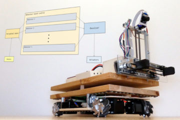
After I presented the hardware architecture in an earlier article, I want to dedicate this article to the software architecture of my mobile robot MOBROB. The software architecture is based on Robot Operating System (ROS), which allows me to extend the robot very modularly by functions. There are a lot of already developed modules that can be easily integrated into my robot.
The Robot Operating System (ROS) is a set of software libraries and tools that help you build robot applications. From drivers to state-of-the-art algorithms, and with powerful developer tools, ROS has what you need for your next robotics project. And it’s all open source.
ros.org
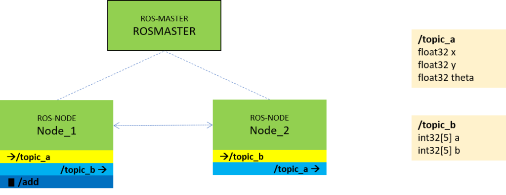
The concept of ROS software architecture is to divide the software into different function blocks, so-called nodes. In the middle is the ROSMASTER, with which the nodes must register at the start. The nodes can be self-written or already developed by third parties. ROS supports the programming languages Python and C++, so that already existing programs can be integrated very easily.
Nodes communicate with each other by publishing messages to topics (e.g. /cmd_vel). A message is a simple data structure consisting of typed fields. Standard primitive types (integer, float, boolean, etc.) and arrays of primitive types are supported. Messages can contain arbitrary nested structures and arrays (similar to C structs). Each node can publish messages to arbitrary topics and subscribe to arbitrary topics. Nodes can also exchange a request and response message as part of a ROS service.
For more information on ROS, I recommend the tutorials at http://wiki.ros.org/.
ROS software architecture in MOBROB
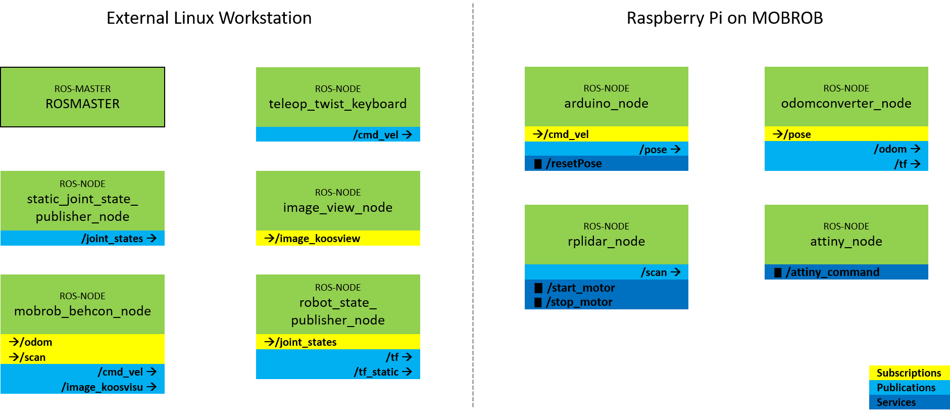
Now let’s see how I implemented ROS on the MOBROB. ROS also allows the nodes to run on different physical computers on the same network. For this reason, it is possible to run the compute-intensive nodes on an external workstation. Therefore I currently have the following setup:
- Raspberry Pi 3 on MOBROB: Ubuntu 16.04. und ROS Kinetic
- External Linux Workstation: Ubuntu 16.04. und ROS Kinetic
Specifically, the breakdown of the basic nodes at MOBROB at the current stage is as follows:
Details of the different nodes
I will introduce the individual nodes below. Some nodes I developed myself, others I took from the standard scope of ROS.
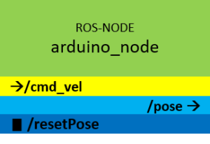
arduino_node
This node controls the wheels of the MOBROB. It consists in detail of two components. On the one hand, I use the standard package rosserial_python to implement a ROS node on an Arduino. So on the Raspberry Pi runs the script serial_node.py, which acts as a gateway for the actual implementation of the node functions on the Arduino Mega. The node listens to the topic /cmd_vel and controls the motors of the Mecanum wheels according to the messages. Messages on the topic /cmd_vel are of type geometry_msgs/Twist and contain speed values for x, y, z and roll, pitch, yaw.
Besides controlling the motors, the node also publishes the position of the robot based on the odometry data on the topic /pose. Since there are no encoders installed, I calculate the position based on the input velocity values. The position can be reset by calling the service /resetPose.
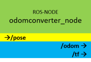
odomconverter_node
The transmission rate on the serial interface between the Raspberry Pi and the Arduino Mega, on which the node arduino_node is executed, is not high enough to send the standardized format for the odometry data. But for the ready available ROS packages, such as the navigation stack, the odometry data is needed in the rich format nav_msgs/Odometry. The odomconverter_node node converts the messages of the topic /pose (format: myrobot_model/Pose) into messages of the topic /odom (format: nav_msgs/Odometry).
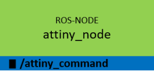
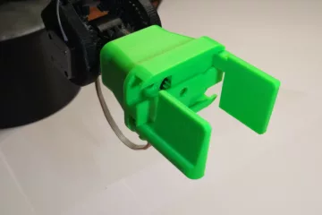
attiny_node
This node is a gateway for communication with the Attiny microcontroller on the MOBROB. The Attiny is responsible for controlling the gripper and the tilt servo for the camera. Via the service /attiny_command, a command can be sent to the Attiny. Since the commands are simply forwarded as a string, all commands are supported which are implemented in the source code of the Attiny.
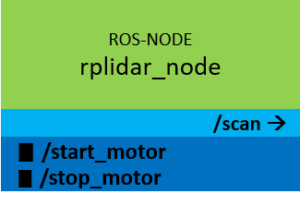
rplidar_node
This node was developed by the company Slamtec, the manufacturer of the laser scanner RPLIDAR A1, which is installed on the robot. It could be easily integrated into the ROS ecosystem and publishes the distance data of the laser scanner via the standardized topic /scan (format: sensor_msgs/LaserScan).
The two services /start_motor and /stop_motor can be used to control the motor of the laser scanner.
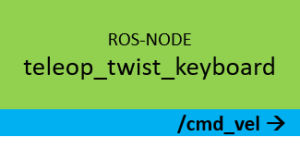
teleop_twist_keyboard
This node is from the standard scope of ROS. It provides a generic remote control for robots, which can be controlled via messages of the type geometry_msgs/Twist. The application is executed in the command line and sends messages via the topic /cmd_vel depending on the keyboard input.
Reading from the keyboard  and Publishing to Twist!
---------------------------
Moving around:
   u    i    o
   j    k    l
   m    ,    .

For Holonomic mode (strafing), hold down the shift key:
---------------------------
   U    I    O
   J    K    L
   M    <    >

t : up (+z)
b : down (-z)

anything else : stop

q/z : increase/decrease max speeds by 10%
w/x : increase/decrease only linear speed by 10%
e/c : increase/decrease only angular speed by 10%

CTRL-C to quit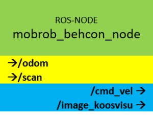
mobrob_behcon_node
This node represents the central component since the behaviour of the robot is programmed here. It is to be considered like the control centre. The node listens as input to the data of the laser scanner (/scan) and the position of the robot (/odom) and publishes speed commands (/cmd_vel) for the actuators of the robot. How exactly this is done I explain in this post.
Besides the speed commands, the node publishes in the current stage a map view from a bird’s eye view for debugging purposes to visualize for example obstacles in the robot environment. This image stream is published as a message on the topic /image_koosvisu (format: sensor_msgs/Image) and can be received by any node.
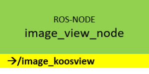
image_view_node
This node is also from the standard scope of ROS. It offers the possibility to display an image stream of a camera or in this case the map view of the node mobrob_behcon_node in a window.
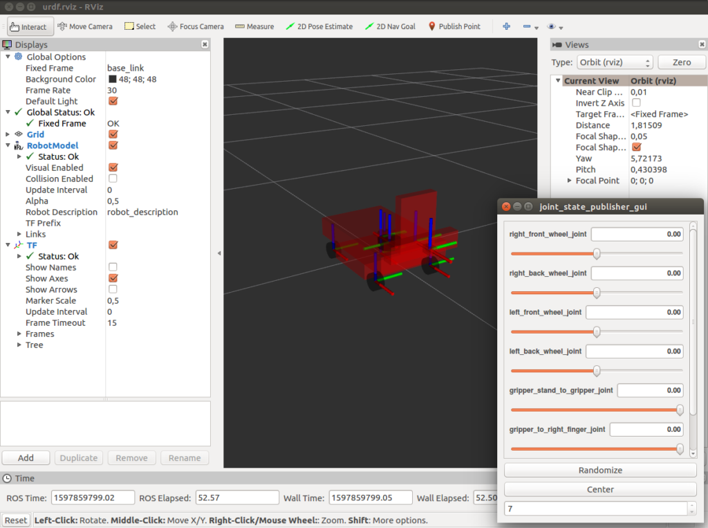
The next two nodes are not essential for the basic use case in its current state but are useful for a complete and consistent overview. I modelled my mobile robot as a digital model using the XML-based language UDRF. This makes it possible to display the robot in the 3D visualization tool RVIZ. To be able to display and move the model simultaneously with the real robot in the visualization, the state of the robot must always be communicated. For this reason, the following two nodes are required.
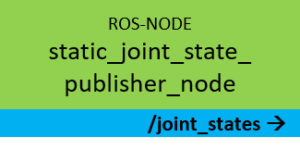
static_joint_state_publisher_node
This node regularly publishes the joint positions of the robot via the topic /joint_states (format: sensor_msgs/JointState). In the case of the mobile robot, these are, for example, the axes of the gripper (vertical, horizontal).
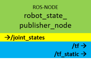
robot_state_publisher_node
This node uses the description of the robot in URDF format and the joint positions from the /joint_states topic to calculate the forward kinematics of the robot and publish the results via the topic /tf (format: tf/tfMessage). This allows the model of the robot to be displayed at any time in the 3D visualization tool RVIZ.
Launch the ROS setup
Since the complete ROS software architecture consists of many modules it is helpful to have a start script that starts all nodes with the correct parameters automatically. In ROS these start scripts called launch-file and look in the basic case for the MOBROB like this:
robot_basic_config_real.launch
<?xml version="1.0"?>
<launch>

	<arg name="gui" default="true" />
	<arg name="rvizconfig" default="$(find myrobot_model)/rviz/urdf.rviz" />

	<param name="use_gui" value="$(arg gui)"/>
	<param name="robot_description" command="$(find xacro)/xacro --inorder '$(find myrobot_model)/urdf/mobrob_move.xacro'"/>

	<machine name="station" address="localhost" env-loader="/opt/ros/kinetic/env.sh" default="true"/>
	<machine name="mobrob" address="MOBROB" timeout="20" env-loader="/opt/ros/kinetic/robot_env.sh" user="myuser" password="mobrob123"/>

	<!-- nodes running on station-->
	<!-- open rviz to visualize the robot state -->
	<node name="rviz" pkg="rviz" type="rviz" args="-d $(arg rvizconfig)" required="true" machine="station"/>
	<node name="robot_state_publisher_node" pkg="robot_state_publisher" type="state_publisher" machine="station"/>

	<!-- send static joint state by own state publisher-->
	<node name="static_joint_state_publisher_node" pkg="mobrob_robotcode" type="mobrob_robotcode_static_joint_state_publisher" machine="station"/>

	<node name="image_view_node" pkg="image_view" type="image_view" machine="station">
		<remap from="image" to="/image_koosvisu" />
	</node>

	<!-- Nodes running on robot-->
	<!-- start node for RPLIDAR-->
	<node name="rplidar_node" pkg="rplidar_ros" type="rplidarNode" output="screen" machine="mobrob">
		<param name="serial_port"         type="string" value="/dev/rplidar"/>
		<param name="serial_baudrate"     type="int"    value="115200"/><!--A1/A2 -->
		<!--param name="serial_baudrate"     type="int"    value="256000"--><!--A3 -->
		<param name="frame_id"            type="string" value="laser"/>
		<param name="inverted"            type="bool"   value="false"/>
		<param name="angle_compensate"    type="bool"   value="true"/>
	</node>

	<!-- start node on Arduino Mega for robot movement and LED control -->
	<node name="arduino_node" pkg="rosserial_python" type="serial_node.py" machine="mobrob">
		<param name="port" value="/dev/arduino" />
	</node>

	<!-- start node for gripper and camera movement-->
	<node name="attiny_node" pkg="mobrob_robotcode" type="attiny_server.py" machine="mobrob"/>

	<!-- start node for converting /pose to /odom topic and publish /odom to /baselink transformation-->
	<node name="odomconverter_node" pkg="mobrob_robotcode" type="mobrob_robotcode_odom_converter" machine="mobrob"/>

</launch>
You can see how I first define a few parameters and the two machines (mobrob and station). Afterwards, the nodes will start on the corresponding machines.
To execute this launch file you just need to run following command in terminal
roslaunch myrobot_model robot_basic_config_real.launch
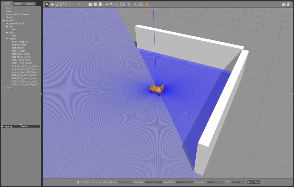
Simulation with Gazebo
Another great advantage of ROS is the possibility to simulate a robot in a virtual environment with only a few steps. I use the program Gazebo, which needs the kinematic description of the robot and a described environment (world) to simulate the robot with actuators and sensors. As long as the virtual robot is described well enough, it behaves like its real model. It reacts to driving commands and publishes corresponding sensor readings. The advantages of such a simulated robot are obvious:
- it is very easy to create or change an environment (world).
- there can be no damage to the robot if errors occur during debugging.
- development can take place independent of hardware and location.
- it can be developed in teams on several components at the same time.
- any disturbance variables, such as sensor noise, can be simulated and thus the algorithms can be optimized.
I have extended the URDF model of the robot to a xacro model to also add the physical properties, such as mass and moments of inertia, of the robot components. The environment (world) is also described as an XML-based file (.world). Also here the definition of physical properties is necessary to make the simulation as realistic as possible. I have created a small world with only two walls here for first testing purposes:
https://github.com/techniccontroller/MobRob_ROS_gazebo/blob/main/worlds/mybot.world
Also to start the simulated setup with Gazebo I created a lauch-file which looks like this:
robot_basic_config_sim.launch
<?xml version="1.0"?>
<launch>

	<!-- start gazebo -->
	<include file="$(find mobrob_gazebo)/launch/myrobot_world.launch" />

	<arg name="rvizconfig" default="$(find myrobot_model)/rviz/urdf.rviz" />

	<!--param name="robot_description" command="cat $(find myrobot_model)/urdf/mobrob_move.urdf" /-->
	<param name="robot_description" command="$(find xacro)/xacro --inorder '$(find myrobot_model)/urdf/mobrob_move.xacro'"/>


	<!-- nodes running on station-->
	<!-- open rviz to visualize the robot state -->
	<node name="rviz" pkg="rviz" type="rviz" args="-d $(arg rvizconfig)" required="true"/>
	<node name="robot_state_publisher_node" pkg="robot_state_publisher" type="state_publisher"/>

	<!-- send static joint state by own state publisher-->
	<node name="static_joint_state_publisher_node" pkg="mobrob_robotcode" type="mobrob_robotcode_static_joint_state_publisher"/>

	<node name="image_view_node" pkg="image_view" type="image_view">
		<remap from="image" to="/image_koosvisu" />
	</node>

</launch>
Run the following command to execute the launch file. This will automatically start Gazebo and load the world and robot model.
roslaunch myrobot_model robot_basic_config_sim.launch
Source code on GitHub
I published all source code of the project on GitHub in different repositories. I want to give an overview of how the repositories are structured:
techniccontroller / MobRob_Arduino
Source code for Arduino Mega and Attiny for MOBROB
techniccontroller / MobRob_ROS_robotcode
ROS-Package: mobrob_robotcode. Includes source code for following nodes:
- attiny_node
- odomconverter_node
- static_joint_state_publisher_node
techniccontroller / MobRob_ROS_myrobot
ROS-Package: myrobot_model. Includes following components:
- visual model of MobRob with movable joints: urdf/mobrob_move.urdf
- visual model of MobRob with fixed joints: urdf/mobrob_fixed.urdf
- own service descriptions for Mobrob: srv/AttinyCommand.srv
- own topic descriptions for MobRob: msg/Pose.msg
- xacro model of MobRob with inertial properties for gazebo simulation: urdf/mobrob_move.xacro
- launch file for MobRob (real robot): launch/robot_basic_config_real.launch
- launch file for MobRob (simulated robot): launch/robot_basic_config_sim.launch
techniccontroller / MobRob_ROS_behcon
ROS-Package: mobrob_behcon. Includes source code and documentation for behaviour based control of MobRob.
Sphinx documentation: https://techniccontroller.github.io/MobRob_ROS_behcon/
techniccontroller / MobRob_ROS_gazebo
ROS-Package: mobrob_gazebo. Includes world and launch files for Gazebo simulation of MobRob.
0 Comments