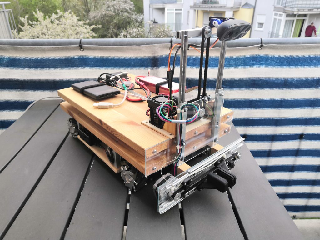
After a long time has passed, here is an update on the current major project MOBROB. My completely self-built mobile robot. In the last post, I introduced the basic functions. The next step is to place the complete electronics nicely on the robot, so that there is still enough space for future constructions, like a gripper unit. In this post, I present the current state of the hardware.
Block Diagram
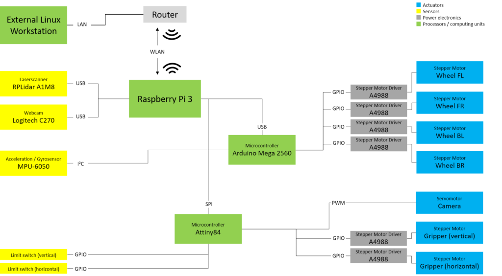
For better understanding, I have created a block diagram to show how the hardware components are connected.
Lidar
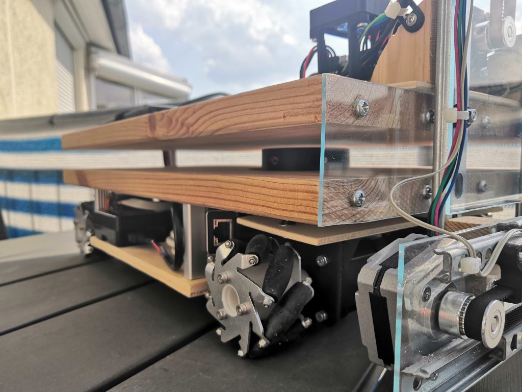
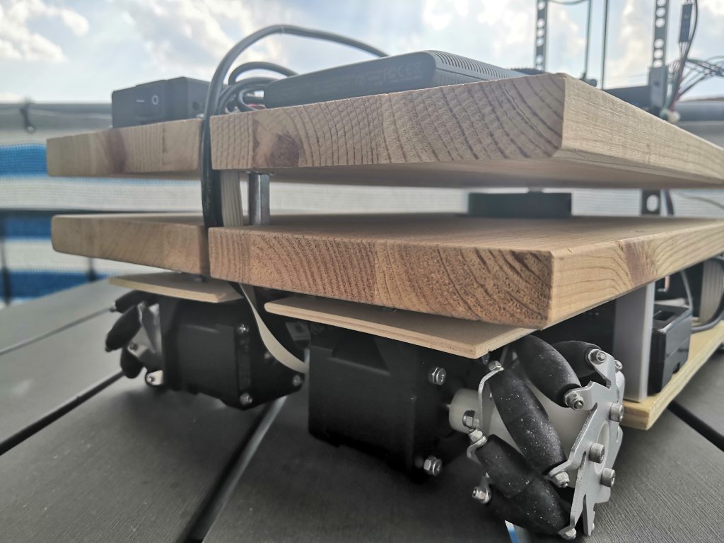
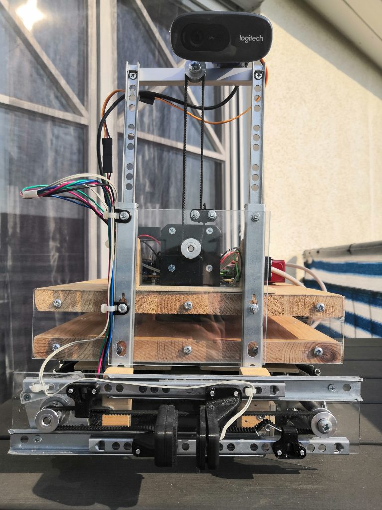
Firstly, the 360-degree lidar sensor poses a small problem because no matter how it is installed, a blind spot cannot be avoided. The best solution, in my opinion, is to position the lidar between two wooden boards and to connect the two boards in the front by a plexiglass plate. In this way, the laser scanner can look through the plexiglass without any problems. Since inevitably some cables have to be led from the bottom to the top of the robot, I attach a small pillar at the back of the robot, in whose ‘shadow’ all cables can be hidden. This reduces the blind spot to a minimum (< 5°). The laser scanner itself is connected to the Raspberry Pi via USB.
Gripper Unit
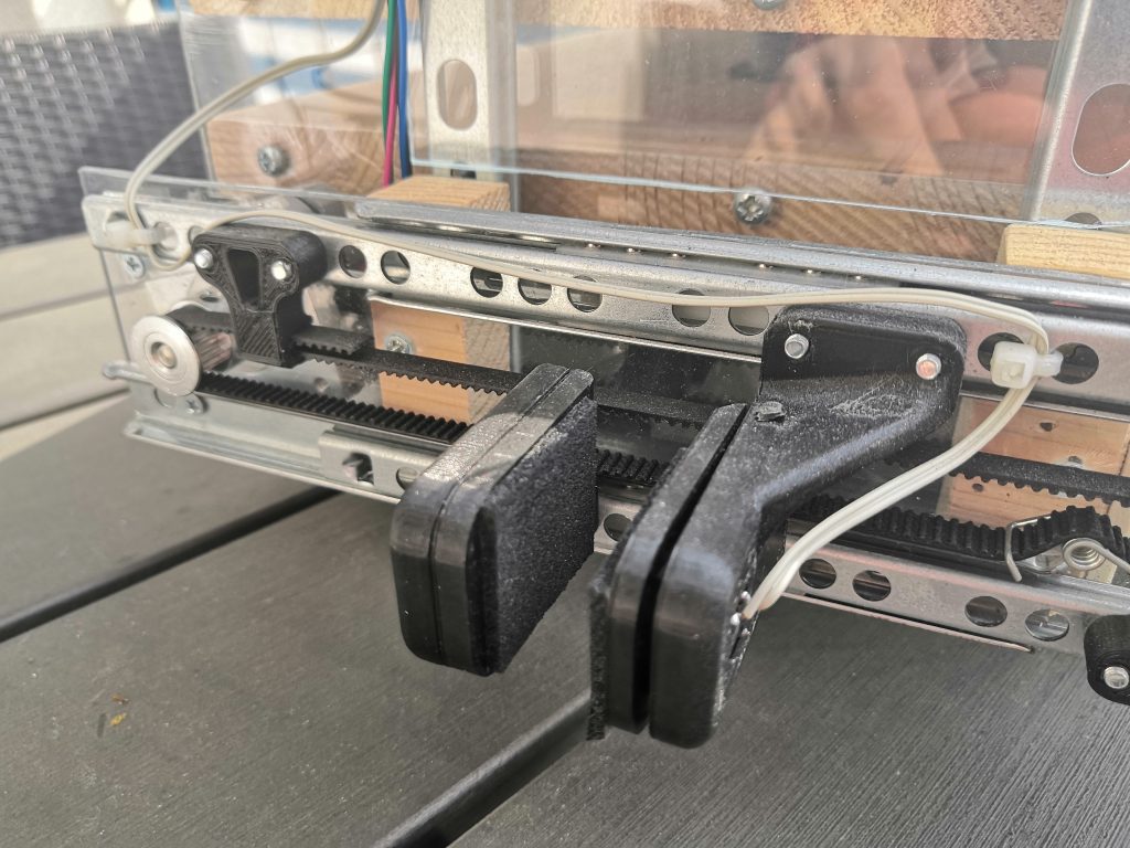
Mechanics of gripper unit
My robot definitely needs a gripper unit. I decided to build a simple parallel gripper. Since I would like to design the gripper unit completely by myself and as inexpensively as possible, I use two drawer guides to guide the linear axes. You can find these drawer guides in every hardware store. Two plexiglass plates, a few wooden blocks and two gripper jaws from the 3D printer complete the gripper unit.
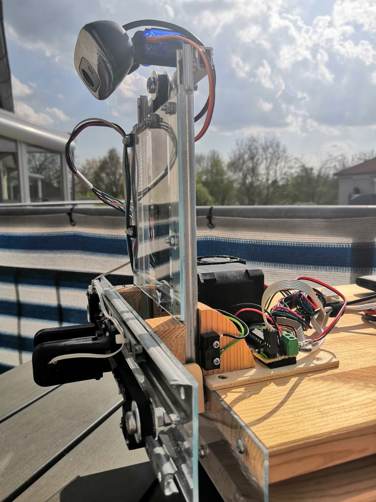
When designing the gripper, it is important to ensure that it can be raised far enough to allow the laser scanner to look underneath the gripper. I solved the control of the two axes with a toothed belt and a stepper motor each. Since the motor for the horizontal axis is moved up and down with it, its weight must be taken into account here. For this reason, I use a small Nema 17 Bipolar 1.8deg with 13Ncm. For the vertical axis, I use the same stepper motor as for the drive axes of the robot (Nema 17 Bipolar 59Ncm).
To determine the initial position of the gripper, the two axes require a limit switch. I installed a limit switch on the vertical axis, which marks the upper-end position as the initial position. On the horizontal axis, the limit switch is located in the left gripper jaw and detects contact with the other gripper jaw here. This means that I can use the limit switch also to detect the object during gripping.
Electrical of gripper unit
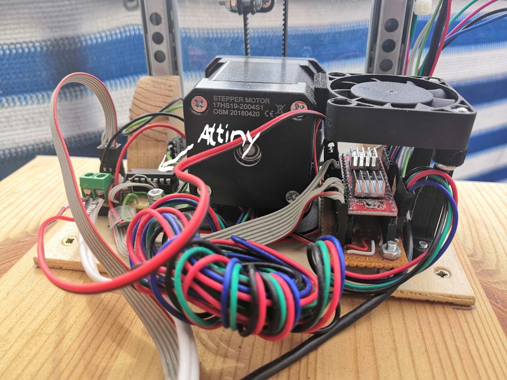
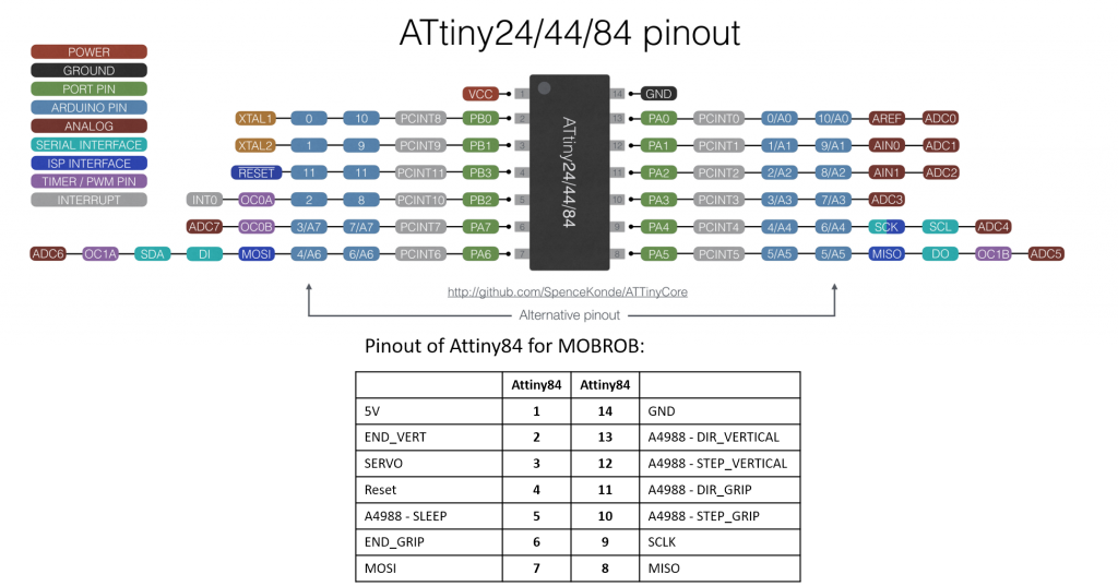
In order to keep the gripper unit modular and the cabling to a minimum, I use a separate microcontroller to control the motors. I use an Attiny84 for this purpose because it is perfectly suited for this task with its small size. I connect the Attiny to the Raspberry Pi via SPI, so that it can receive its control signals and can be flashed.
As already shown in my first post, I need a motor driver for the control of the stepper motors. As already known from the drive axes I use the A4988 as the stepper motor driver. In addition, I connect each of the two limit switches to a GPIO of the Attiny. Besides the control of the gripper, the Attiny also controls the servo motor, which can change the angle of view of the camera. In total, all possible pins of the Attiny are used and the flash memory is 90% full.
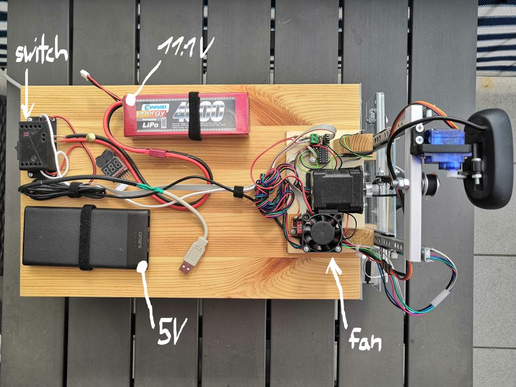
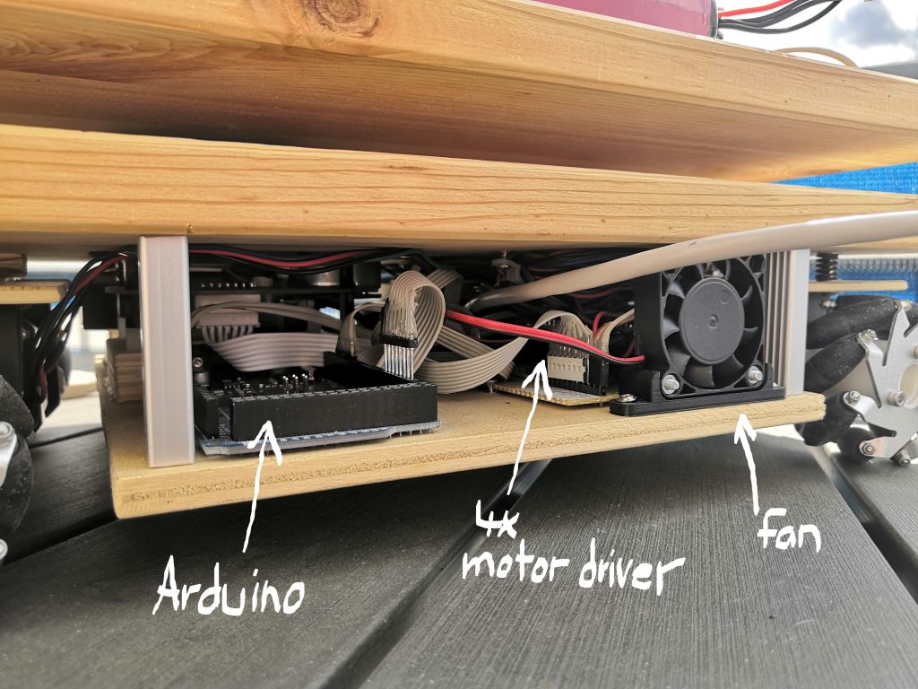
Power Management
For the robot, I use two different power sources. On the one hand, a USB power bank with a maximum output power of 15W provides 5V. These 5V supplies the Raspberry Pi and its sub-participants (Arduino, Lidar, Attiny, …). The second power source is a 3S Lipo battery with a capacity of 4000mAh with around 11.1V. This power source supplies the high current consuming actuators. Due to the separation of the power sources, the actuators do not influence the power supply of the whole system. I also added a switch to switch off the actuator voltage separately. Especially during gripper operation, the motors are often in stall mode, in which the motor drivers become very hot. To cool down the motor driver, I mounted two fans, which are also supplied by the actuator voltage.
In the next post, I will present the software architecture of this robot, which I build with ROS. Stay tuned, this gone be very interesting.

0 Comments