This post summarizes the steps to program an ESP8266 with its own program written with Arduino IDE. I used the ESP8266 for example in the project MANU – 3D printed robot hand.
Installation of Arduino IDE
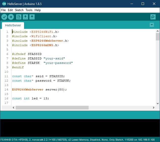
First, the latest version of the Arduino IDE needs to be downloaded and installed from here.
Installation of ESP8266 Arduino Core
To program the ESP8266 with the Arduino IDE, you need to install the board information first in Arduino IDE. To do that follow following instructions:
- Start Arduino and open the Preferences window.
- Enter http://arduino.esp8266.com/stable/package_esp8266com_index.json into the Additional Board Manager URLs field. You can add multiple URLs, separating them with commas.
- Open Boards Manager from Tools > Board menu and find esp8266 platform.
- Select the version you need from a drop-down box.
- Click the install button.
- Don’t forget to select your ESP8266 board from Tools > Board menu after installation.
You find this guide also here: Installing — ESP8266 Arduino Core 3.0.0-15-g325619a4 documentation (arduino-esp8266.readthedocs.io)
Installation of ESP8266FS
You can save files on the filesystem of the ESP8266 Board. To upload files to this file system you can use the tool ESP8266FS. ESP8266FS is a tool that integrates into the Arduino IDE. It adds a menu item to the Tools menu for uploading the contents of the sketch data directory into the ESP8266 flash file system.
- Download the tool: Download ESP8266FS-0.3.0.zip from GitHub
- In your Arduino sketchbook directory, create a tools directory if it doesn’t exist yet
- Unpack the tool into the tools directory (the path will look like <home_dir>/Arduino/tools/ESP8266FS/tool/esp8266fs.jar)
- Restart Arduino IDE
- Open a sketch (or create a new one and save it)
- Go to sketch directory (choose Sketch > Show Sketch Folder)
- Create a directory named data and any files you want in the file system there
- Make sure you have selected a board, port, and closed Serial Monitor
- Select Tools > ESP8266 Sketch Data Upload. This should start uploading the files into the ESP8266 flash file system. When done, the IDE status bar will display SPIFFS Image Uploaded message.
You find this guide also here: Filesystem — ESP8266 Arduino Core 3.0.0-15-g325619a4 documentation (arduino-esp8266.readthedocs.io)
Hardware versions of ESP8266
The ESP8266 is available in many different hardware variants, which differ mainly in the number of pins available. I would like to briefly introduce the three most important variants here:
ESP8266 ESP-01 Module
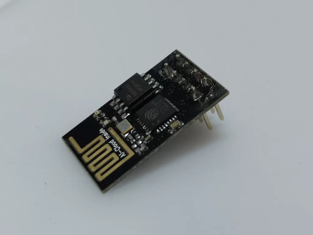
The ESP8266 ESP-01 Module has only four digital GPIOs (with PWM) available. There is no Micro-USB port included. So to flash a program onto the chip a separate USB-to-TTL serial adapter is required (see next section).
ESP8266 NodeMCU V3
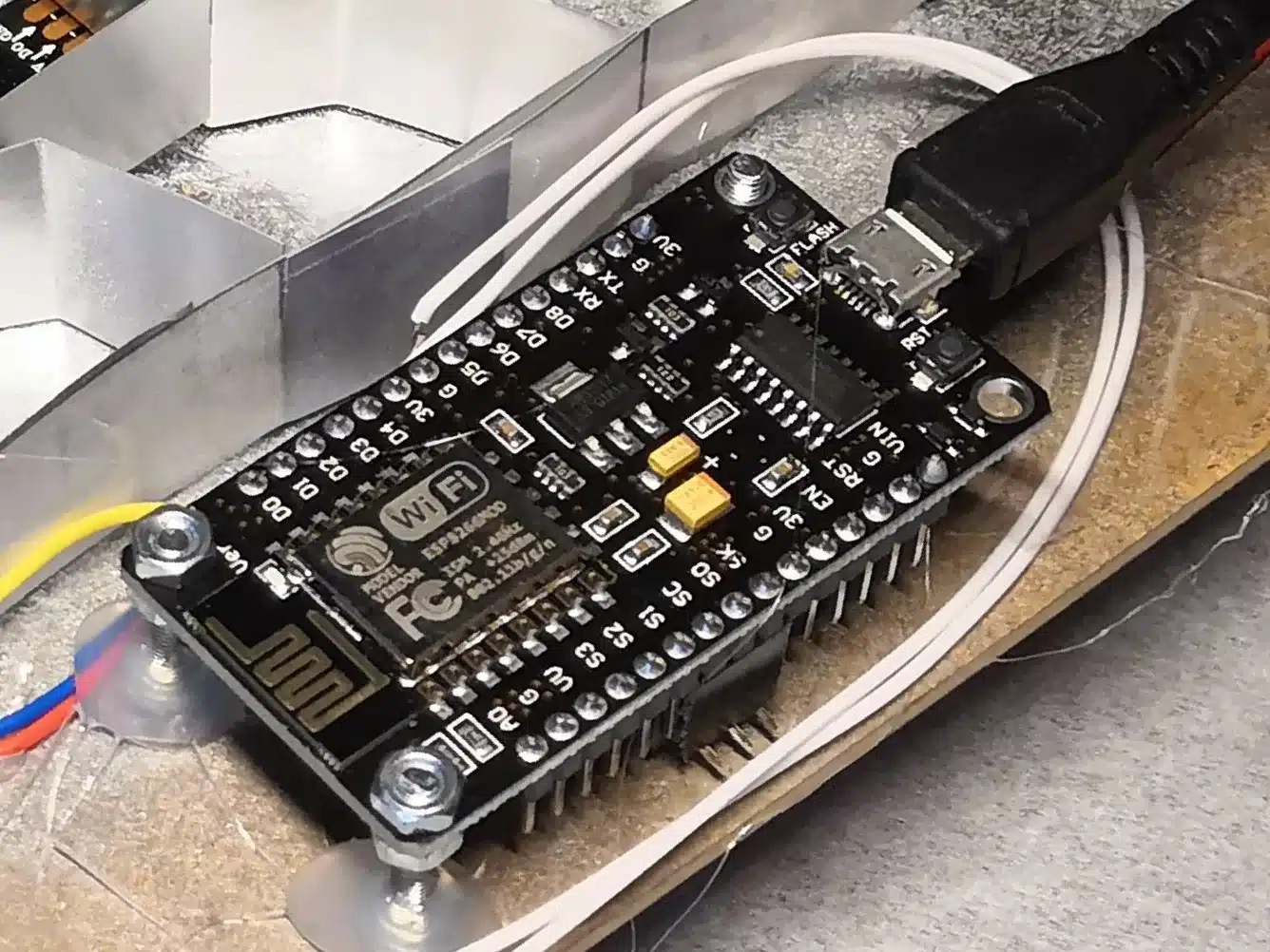
The ESP8266 NodeMCU V3 Module has a Micro-USB port and can be programmed directly with a computer. There are 10 digital GPIOs (with PWM) and one analog input pin available. The other pins provide direct access to the flash memory but are in most applications not required.
ESP8266 D1 Mini
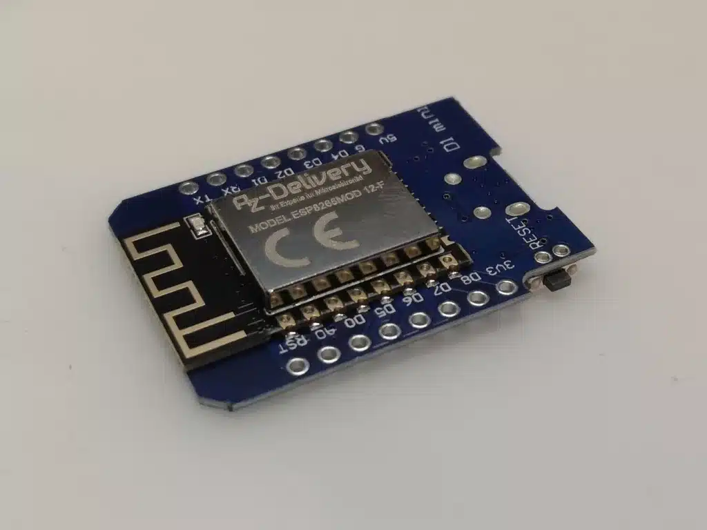
The ESP8266 D1 Mini Module has a Micro-USB port and can be programmed directly with a computer. There are 10 digital GPIOs (with PWM) and one analog input pin available.
Hardware setup for flashing ESP8266 ESP-01
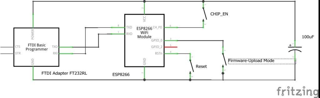
As the ESP8266 ESP-01 does not have a USB port you need to use some additional components for flashing:
- ESP8266 ESP-01 Module
- FTDI Adapter FT232RL USB to TTL Serial for 3,3V and 5V
- Own build adapter PCB
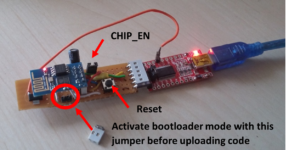
Instead of little buttons/switches, I used simple jumpers in the real PCB for the CHIP_EN and bootloader mode pins.
Upload a program to ESP8266 ESP-01
- Mount the jumpers on the PCB to activate bootloader mode and enable the chip.
- Connect your ESP8266 Board via the FTDI Module to your computer (see chapter Hardware setup).
- Open your program in the Arduino IDE.
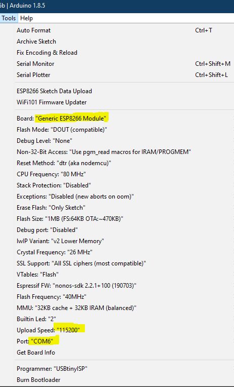
- Select Tools->Board->Generic ESP8266 Module.
- Set the Upload speed to 115200.
- Make sure the right Port is selected.
- Click on the upload button in the Arduino IDE to upload the program to the ESP8266 Module.
After upload, you can remove the bootloader mode jumper on the PCB and press the reset button to get out of the bootloader mode.
Upload program to ESP8266 NodeMcu V3 and D1 Mini
For the modules with integrated USB-to-TTL serial adapters such as NodeMCu V3 or D1 Mini, uploading a program is a bit easier. You only have to select the corresponding board in the Arduino IDE (ESP8266 NodeMcu V3 or ESP8266 Wemos D1 Mini) and then start the upload directly in the Arduino IDE. Of course, you should select the correct COM port and set the upload speed to 115200.
Code – Examples
You can find some code examples here:
- https://github.com/esp8266/Arduino/tree/master/libraries/ESP8266WiFi/examples
- https://github.com/esp8266/Arduino/tree/master/libraries/ESP8266WebServer/examples
- https://techtutorialsx.com/2016/10/03/esp8266-setting-a-simple-http-webserver/
- https://github.com/projetsdiy/ESP8266-Webserver-Tutorials/tree/master/Tuto1_DHT22WebserverESP8266_SPIFFS (Webserver with index.html in filesystem)
Flash firmware to ESP8266 (.bin files)
This is what I did to flash my ESP8266 – 01 from my windows pc
– Wire it up like this
– Install python 2.7 download here
– Install pyserial download here
– Download to the esptool.py from here save it in the pyton installation folder
– Build and download your nodemcu_latest.bin from here and save it in the python installation folder
– Edit esptool.py so that:
ESP_RAM_BLOCK = 0x180
ESP_FLASH_BLOCK = 0x40
– Open cmd and go to the python folder and type in this (change the COM7 to whatever your FTDI is)
esptool.py -p COM7 write_flash 0x000000 nodemcu_latest.bin
References
ESP8266 und ESP8285 Module Anleitung (stefanfrings.de) -> more information about ESP8266 (pinning, schematics, variants, AT firmware, ….)
ESP8266 Over The Air (OTA) Programming In Arduino IDE – 3 Steps (lastminuteengineers.com) -> guide/information about OTA update of ESP8266
ESP AT firmware: https://www.espressif.com/en/support/download/at
ESP firmware: https://github.com/Edragon/esp_firmware
Good Tool to write lua code and send AT commands: https://github.com/4refr0nt/ESPlorer

2 Comments
Manuel · 05/01/2024 at 19:59
Hi, ich bastel gerade die zweiter Version Deiner Uhr und stelle mir die Frage, ob ich den selbst gebastelten Adapter überhaupt noch benötige, da das ESP8266 NodeMCU V3 doch jetzt einen USB Anschluss hat.🤔
Vielen Dank im Voraus und Grüße Manuel
Techniccontroller · 05/01/2024 at 20:33
Hallo Manuel,
ja genau wenn du den ESP8266 NodeMCU V3 verwendest, braucht man den FTDI Adapter natürlich nicht. In dem Artikel zur Wortuhr 2.0 habe ich ja auch mit einem ESP8266 NodeMCU V3 Module gearbeitet.
Ich habe es nur auf dieser Seite hier noch recht allgemein mit Adapter, falls man nur das ESP8266 ESP-01 Modul hat. Danke für den Hinweis. Ich werde es hier auf der Seite nochmal genauer beschreiben.
Viele Grüße
Edgar