In this article, I document the few steps necessary to control the Wi-Fi switch Shelly 1 with a Siemens LOGO! 8. For this we use the help of the tool Node-RED, which is described on the own website as follows and is therefore perfectly suited for our use-case:
Node-RED is a programming tool for wiring together hardware devices, APIs and online services in new and interesting ways.
https://nodered.org/
Components
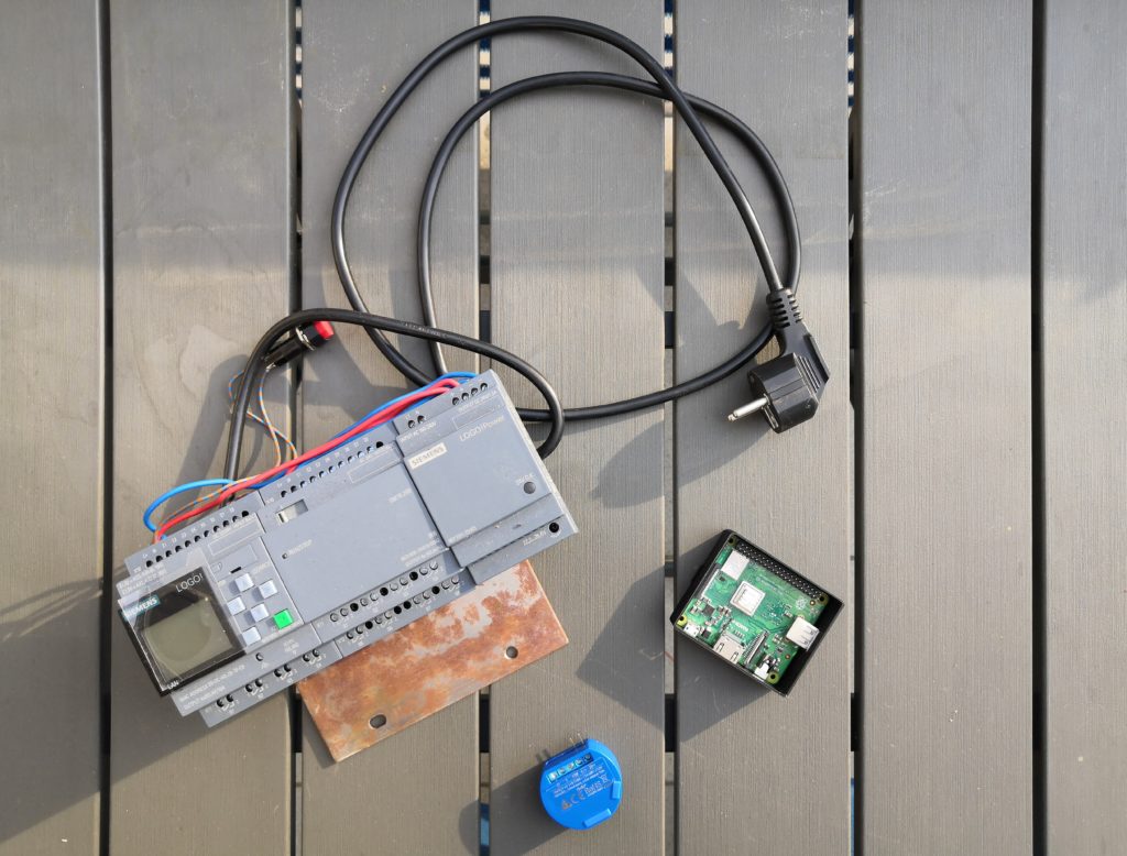
These are the main components we need for the project:
- Shelly 1 Wi-Fi Switch
- Siemens LOGO! 8 Basic Starter Kit (LOGO! 8 + Powersupply + LOGO! Soft Comfort V8)
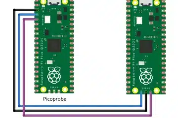
- Raspberry Pi 3 Model A+
Architecture
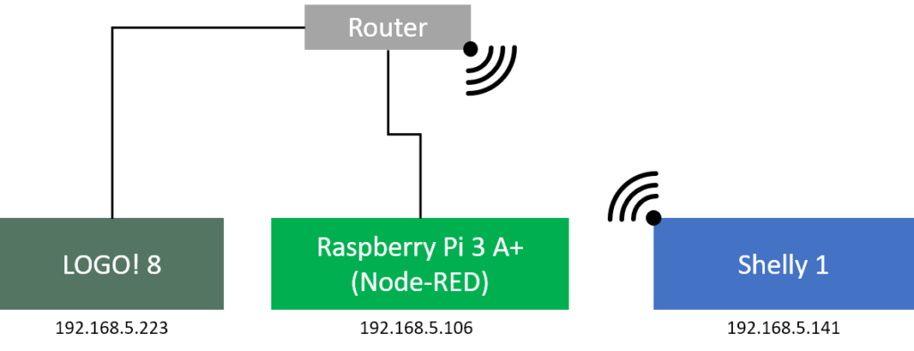
The signal flow is quite simple. The LOGO! mirrors the state of the digital input to Node-RED. In Node-RED we can further process the state, for example, display it in a dashboard or forward it to the Wi-Fi switch Shelly 1. The Shelly 1 then controls the actuator.

In practice, Node-RED is installed on Raspberry Pi. The Raspberry Pi and LOGO! 8 are connected to a router via Ethernet cable. The Shelly is connected to the same network via Wi-Fi.
Shelly 1
With the Shelly we don’t need to do a lot. We just need to make sure that it is in client mode and connected to the same network as the LOGO! and the Raspberry Pi.
LOGO! 8
For our example some preparations are necessary. First of all, we mount a switch to input I1, which can connect the 24 Volt to the input. In order to establish communication between the LOGO! and Node-RED, the LOGO! must be configured to allow external access. This is done with a right-click on the LOGO! and the menu item Add server connection -> S7 Connection.
Here we configure the new server connection. The following figure shows which parameters we must set so that the LOGO! allows external access.
Once you have clicked OK, the variables of LOGO! can be read and written. The variables are all one byte wide. This means that eight digital states fit into one byte. Our program on the LOGO is pretty simple. We save the input value of I1 into the variable V4.0. In the following figure, you can see the whole program. I add also a second input, which I save in variable V4.1 but this is not needed for our example.
The LOGO! part is now ready, let’s see what we need to do to get Node-RED running on the Raspberry Pi.
Node-RED
First let’s install Node-RED on our Raspberry Pi:
bash <(curl -sL https://raw.githubusercontent.com/node-red/linux-installers/master/deb/update-nodejs-and-nodered)
This will install Node.js, npm, and Node-RED onto the Raspberry Pi. With the following command we start Node-RED as service:
sudo systemctl start nodered.service
To access the Node-RED editor we are now open a browser and navigate to http://<raspberry>:1880/.
First, we have to install three modules. To do this, we go to Settings -> Palette -> Install and search for the following modules, which we then install directly:
- node-red-contrib-s7
- node-red-contrib-shelly
- node-red-dashboard
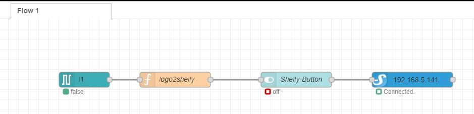
After installing the modules we now have some more nodes to choose from on the left side. For our example we only need four nodes, which I explain in detail in the following:
Node: s7 in
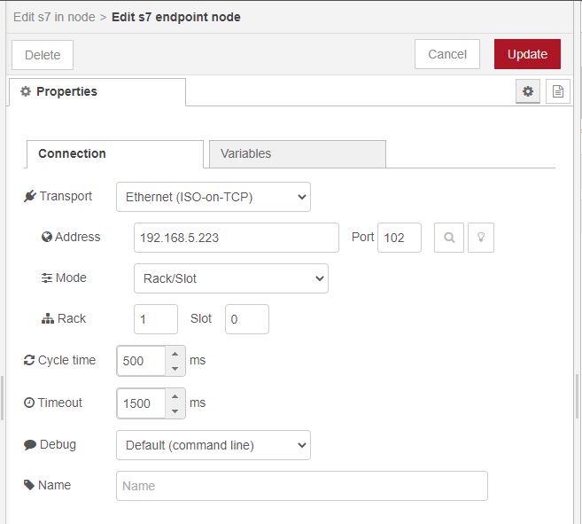
We start with the node s7 in from the plc category and place it on the Flow tab. To edit the node, we double click on it. Here you can see the window for editing the node.
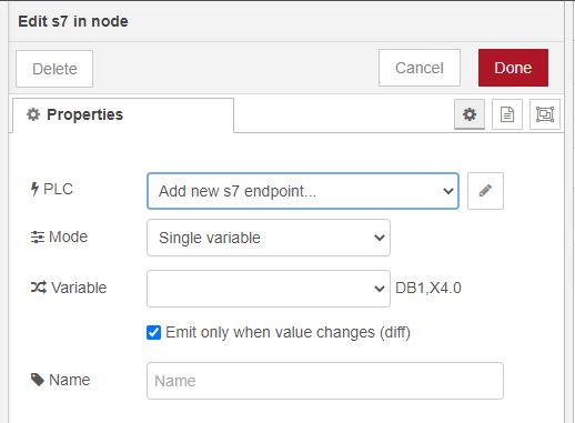
We click on the pencil icon to the right of Add new S7 endpoint… to create a new endpoint. An endpoint is a data connection to an external device that can transmit messages. Here we now enter the IP address of our LOGO! Please make sure that Rack has a 1 and Slot has a 0. The port remains at 102.
Now we switch to the tab Variables and create the following variable. If we have multiple inputs we would have to create a separate variable for each input.
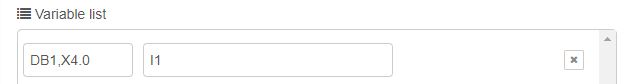
After that, we click on Update and automatically return to the page for creating endpoints. Here we can now select under Mode whether we want to read all variables or only a specific one from the LOGO! We select the mode Single variable and as a variable, we select the variable I1. We have now fully configured this node. Click on Done to close the window.
Node: function
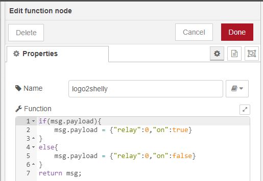
The output of the S7 node consists of a message with a topic and a payload. The payload represents the state of the input. Unfortunately, the payload of the S7 node does not correspond to the data format we need to control the Shellys. The payload of the S7 node is a boolean value with true or false. But the shelly node needs a JSON object as payload. For this reason, we now insert a node function into our flow. This node must convert the data format of the payload.
With a double click on the node, we can define a Javascript code for the conversion. We first check the payload and then change the payload accordingly.
Node: dashboard switch
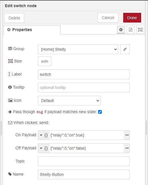
To display the data available in Node-RED, there is the Dashboard. We can place different nodes for display. As we have a boolean value to display we choose the node switch and place it on the flow. The important properties of this node are the On Payload and Off payload. Here we need to enter the JSON expression for switch the Shelly ON or OFF. Therefore we select JSON from the dropdown and enter the following into the fields:
To display the switch on the Dashboard (accessible via http://<raspberry>:1880/ui/) we need to add a new ui_group and ui_tab. The easiest way is to click on the pencil icon next to Add new ui_group… and Add new ui_tab… on the next window. By clicking on Add the ui_tab or ui_group is created.
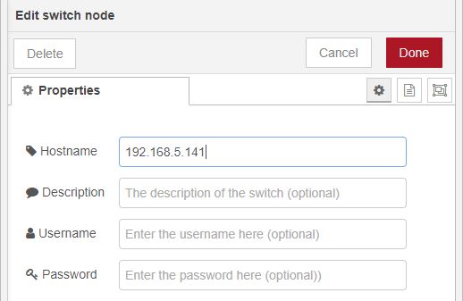
Node: shelly switch
Finally lets put the last node on the flow: the Shelly switch node. Here we just need to enter the IP address of the Shelly and we are ready to go.
Let’s test our setup! After a click on Deploy, we should be able to control the relay on the Shelly with the switch attached to I1 of the LOGO!. At the same time, we can control the relay via the switch on the dashboard.
References
https://flows.nodered.org/node/node-red-contrib-shelly
https://nodered.org/docs/getting-started/raspberrypi
https://entwickler.de/online/iot/node-red-logo-579874813.html


0 Comments